
Related Manuals for SNBC BK-T6112


Summary of Contents for SNBC BK-T6112
- Page 1 Service Manual Embedded Printer BK-T6112 Shandong New Beiyang Information Technology Co., Ltd.
- Page 2 BK-T6112 Service Manual Revision records Date Version Description Author Song Zhenhua, Wang Xinping, 2013-1-16 Initial draft Li Xiaochun, Wang Jing - 1 -...
- Page 3 BK-T6112 Service Manual Declaration This manual is special for embedded printer BK-T6112 and it is not allowed to be modified without permission. Shandong New Beiyang Information Technology Co., Ltd. (hereinafter referred to as “SNBC”) reserves the right to improve products as new technology, components, software, and firmware available. If users need the further data about these products, please feel free to contact SNBC or our distributors.
- Page 4 BK-T6112 Service Manual Notes: Follow the steps in this manual hereafter during maintenance. Make sure that the printer and the computer are turned off before plugging the communication cable, changing print head or doing maintenance to the printer. Take anti-static measures when replacing print head or other electronic components.
-
Page 5: Table Of Contents
BK-T6112 Service Manual Contents 1 Printer Characteristics ..........................1 1.1 Brief introduction ..........................1 1.2 Function .............................1 1.3 Technical specification ........................3 1.4 Button & LED............................4 1.4.1 Button............................4 1.4.2 LED .............................4 1.5 Interface parameters ..........................5 1.5.1 USB interface ..........................5 1.5.2 Serial interface ..........................6 2 Printer Overview and Modules ........................8... - Page 6 BK-T6112 Service Manual 4.1.3 Caution............................19 4.2 Platen roller maintenance and replacement ..................19 4.2.1 Platen roller maintenance......................19 4.2.2 Platen roller replacement ......................20 4.2.3 Caution............................21 4.3 Microswitch replacement........................22 4.3.1 Microswitch replacement......................22 4.3.2 Caution............................22 4.4 Sensor replacement .........................22 4.4.1 Mark sensor replacement......................22 4.4.2 Paper end sensor replacement ....................23 4.4.3 2-side detection sensor replacement ..................24...
- Page 7 BK-T6112 Service Manual Appendix ..............................34 Appendix 1 Product naming rule ......................34 Appendix 2 EEPROM setting table......................35 Appendix 3 MemSwitch setting table......................36 Appendix 4 Command set ........................37 Appendix 5 Spare parts list ........................39 Appendix 6 Printer exploded view ......................44 Appendix 7 Parts list..........................54 Appendix 8 Overall dimension........................59...
-
Page 8: Printer Characteristics
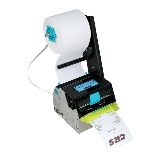
Presenter LED paper outlet module Cantilever paper holder Control board Cutter BK-T6112 can connect with other equipments through serial + USB interface, and it also provides drivers under WINDOWS2000/XP/2003/Vista/2008/Win7/Windows XP Embedded and software package based on DLL. 1.2 Function Printing... - Page 9 BK-T6112 Service Manual Repeat operation and duplicate printing by macro definition. Maintenance Convenient to replace paper roll; Different characteristics and parameters can be set through software; Automatic paper cutting; Semi-automatic paper loading; Mark recognition and calibration; Printer firmware on-line updating.
-
Page 10: Technical Specification
BK-T6112 Service Manual 1.3 Technical specification Item Parameter Print method Thermal Resolution 203/305DPI Paper width 79.5~112±0.5 mm Max.104mm (4.1 ") Print width Max.832 dots (203DPI) Max: 800 mm Print height Min: 80 mm 203DPI 1ST (Max): 200mm/s 203DPI 2ST(Max): 100mm/s... -
Page 11: Button & Led
BK-T6112 Service Manual 1.4 Button & LED 1.4.1 Button FEED button Print self-test page: Press the paper FEED button for three seconds while turning on the printer, the printer will print self-test page. Feed paper: In normal status, the printer starts feeding paper while pressing down the feed button;... -
Page 12: Interface Parameters
BK-T6112 Service Manual 1.5 Interface parameters 1.5.1 USB interface The USB interface is the standard interface of BK-T6112, complying with the USB 2.0 protocol and working in full speed mode. 1.5.1.1 USB interface signal definition and function description Pin No. -
Page 13: Serial Interface
BK-T6112 Service Manual 1.5.2 Serial interface The printer serial interface is compatible with the RS-232 protocol, using 9-pin female DSUB-9 serial interface connector. 1.5.2.1 Serial interface signal definition The definition of the interface signal is as shown in the following table: Pin No. - Page 14 BK-T6112 Service Manual 1.5.2.4 Serial interface parameter The serial interface parameters are shown as below: Item Parameter Data transmission Serial Synchronous mode Asynchronous transmission Handshaking mode RTS/CTS MARK = -3 to –15 V: logic 1/ OFF Voltage SPACE = +3 to +15 V: logic 0/ ON...
-
Page 15: Printer Overview And Modules
BK-T6112 Service Manual Printer Overview and Modules 2.1 Printer overview Figure 2.1-1 BK-T6112 printer overview 1 —Paper near end sensor 3 —Top cover locking axis 2 —LED paper out path 4 —Cover open spanner socket 1 7 —Mark scale 8 —Paper near end sensor 5 —Button LED... -
Page 16: Main Control Board Unit Block Diagram
BK-T6112 Service Manual 2.2 Main control board unit block diagram This printer adopts KSKT1V1.2 main control board, various components of the printer like sensors, buttons, print head, motor, cutter and paper-out module are connected to the controller board through connectors or transfer board, as shown in the diagram below. -
Page 17: Disassembly And Assembly
BK-T6112 Service Manual Disassembly and Assembly Notes: Do not disassemble any part of the printer and do not loosen any screw of it when it works properly. When disassembling or assembling the spare parts, check wires and cables for any damages. -
Page 18: Disassemble The Paper Guide's Cover Module
BK-T6112 Service Manual Figure Description Disassemble the two M3×6 screws and the two Φ3 elastic washers with the cross screw driver, and then take off the motor module. Note: When taking off the motor module, pull the motor cable out of main control board. -
Page 19: Disassemble The Print Motor Module
BK-T6112 Service Manual Figure Description Disassemble ST2.6x6 flat self-tapping screws on both side of printer with cross screw driver, and take off the paper guide's cover module. ①—ST2.6×6 flat self-tapping screw ②—Paper guide's cover module ③—Mark sensor adjusting thumbwheel ④—Mark sensor socket... -
Page 20: Disassemble The Led Paper Out Path Module
BK-T6112 Service Manual 3.1.4 Disassemble the LED paper out path module Figure Description Printer overview Turn off the printer power. Disassemble the two M3×6 pan head screws with cross screw driver and then take off the LED paper out path module. -
Page 21: Disassemble The Top Cover Module
BK-T6112 Service Manual Figure Description Press the top cover open spanner in the direction of arrow a and uplift the top cover module in the direction of arrow b. ①—Top cover open spanner ②—Top cover module Follow "3.1.4 Disassemble the LED paper out path module", disassemble the paper... -
Page 22: Disassemble The Platen Roller Holder Module
BK-T6112 Service Manual Figure Description Disassemble the two M3x6 pan head screws with cross screw driver, and take off the two Φ3 spring washers and the top cover module. ①—M3×6 pan head screw ②—Φ3 spring washer ③—Top cover module ④—Starting rotation shaft ⑤—Starting torque spring... -
Page 23: Replacement And Maintenance Of Critical Parts
BK-T6112 Service Manual Replacement and Maintenance of Critical Parts 4.1 Print head maintenance and replacement 4.1.1 Print head maintenance To assure print head lifetime and print effect, print head should be cleaned after using up every paper roll. Figure Description Printer overview Turn off the printer power. -
Page 24: Print Head Replacement
BK-T6112 Service Manual Figure Description After the surface of print head is dry, close the top cover module, and then turn on the printer power. 4.1.2 Print head replacement Upper print head replacement: Figure Description Refer to "3.1.2 Disassemble the paper guide's cover module", disassemble the... - Page 25 BK-T6112 Service Manual Figure Description Pull out the connecting cable of print head. Disassemble the print head fixing screw and the M3x4 spherical cross screw with cross screw driver, move the print head grounding cable and take off the upper print head.
-
Page 26: Caution
BK-T6112 Service Manual 4.1.3 Caution Print head is a thermal part, don’t disassemble it until it cools down completely after finishing printing. The print head tends to be damaged. Please pay attention to avoid touching it or scratching it with hard objects during the disassembly and maintenance. -
Page 27: Platen Roller Replacement
BK-T6112 Service Manual Figure Description Wipe off the surface of platen roller with cotton dipped with alcohol. ①—Surface of lower print head ②—Lower platen roller Wipe off the surface of platen roller with cotton dipped with alcohol. ①—Surface of upper print head ②—Upper platen roller... -
Page 28: Caution
BK-T6112 Service Manual Figure Description Take off the roller gear, disassemble the "E"-rings on both sides of platen roller with nipper pliers, and then take off the roller shaft sleeve and the platen roller on both sides. ①—Roller gear ②—Φ3 "E"-ring ③—Shaft sleeve of platen roller... -
Page 29: Microswitch Replacement
Tools: Cross screw driver, cut plier. 4.4 Sensor replacement BK-T6112 totally has six sensors: mark sensor, paper end sensor, 2-side detection sensor, paper out sensor, retraction sensor, and paper near end sensor. 4.4.1 Mark sensor replacement... -
Page 30: Paper End Sensor Replacement
BK-T6112 Service Manual Figure Description Disassemble the one ST1.7×4 pan head self-tapping screw with cross screw driver, and take off the mark sensor. ①—ST1.7×4 pan head self-tapping screw ②—Mark sensor 4.4.2 Paper end sensor replacement Figure Description Refer to "3.1.7 Disassemble the platen roller holder module", take off the platen... -
Page 31: 2-Side Detection Sensor Replacement
BK-T6112 Service Manual 4.4.3 2-side detection sensor replacement Figure Description Refer to step 4 of upper print head replacement "4.1.2 Print head replacement", then take off the pressure spring supporting plate 1. Disassemble the two M2.5x5 pan head screws with cross screw driver, and take off the visible light sensor. -
Page 32: Retraction Sensor Replacement
BK-T6112 Service Manual 4.4.5 Retraction sensor replacement Figure Description Refer to "3.1.5 Disassemble the Presenter module", disassemble Presenter module. Pull the connector of retraction sensor out of corresponding socket. ①—Retraction sensor socket Note: When taking off the retraction sensor, pull the connector of retraction... -
Page 33: Paper Near End Sensor Replacement
BK-T6112 Service Manual 4.4.6 Paper near end sensor replacement Figure Description Overview of cantilever paper holder. Disassemble the one M4x8 pan head screw with cross screw driver, and take off the paper roll baffle. ①—M4×8 pan head screw ②—Paper roll baffle Disassemble the one ST2.6x6 pan head... -
Page 34: Cutter Replacement
BK-T6112 Service Manual 4.5 Cutter replacement 4.5.1 Cutter replacement Figure Description Refer to "3.1.2 Disassemble the paper guide's cover module", disassemble the paper guide's cover module. Refer to step 2 of "4.2.1 Platen roller maintenance", uplift the top cover module. -
Page 35: Caution
BK-T6112 Service Manual Figure Description Disassemble the four M3x6 pan head screws with cross screw driver, and take off the four cutter fixing washers and the cutter module. ①—M3×6 pan head screw ②—Cutter fixing washer ③—Cutter module Disassemble the two ST2.6x6 pan head... -
Page 36: Motor Replacement
BK-T6112 Service Manual 4.6 Motor replacement Tools: Cross screw driver, nipper plier. 4.6.1 Presenter motor replacement Figure Description Refer to "3.1.5 Disassemble the Presenter module", disassemble the Presenter module. Take off the worm gear. Pull the connector of retraction sensor and... -
Page 37: Printer Adjustment
5.1 Mark sensor position adjustment The mark sensor of BK-T6112 printer can carry out the position adjustment of left/right and thermal side/non-thermal side. When the following cases occur, the position of the mark sensor should be... -
Page 38: Paper Path Width Adjustment
BK-T6112 Service Manual Steps for adjusting the mark sensor (thermal side/non-thermal side) are as follows: Figure Description Follow "3.1.2 Disassemble the paper guide's cover module", disassemble the paper guide's cover module. Disassemble the mark sensor module 1 and the mark sensor module 2, and... -
Page 39: Troubleshooting
BK-T6112 Service Manual Troubleshooting 6.1 Troubleshooting method ERROR LED 200m Status Description PAPER LED Print head Temperature of the print head is too overheating high. Abnormal voltage Input voltage is too high or too low. Cutter error Cutter can’t work normally or Paper Paper jam jams. -
Page 40: Printer Status Description
BK-T6112 Service Manual 6.3 Printer status description Error status Including print head uplifting, paper end, paper near end, abnormal voltage, print head overheating, mark calibration error, paper jam, printer stops printing when paper near end, cutter error and etc; Standby status The printer has no error, does not print and feed paper, and waits for print job;... -
Page 41: Appendix
BK-T6112 Service Manual Appendix Appendix 1 Product naming rule BK – T6112 Model explanation: a: Standard name b: Resolution 203DPI 305DPI c: Interface U: USB S: RS-232 + USB R: RS-232 d: Cutter K: With cutter e: Paper out module... -
Page 42: Appendix 2 Eeprom Setting Table
BK-T6112 Service Manual Appendix 2 EEPROM setting table EEPROM Address Function Range & Description (HEX) Print darkness Two print heads: [range] 1-254,1-254 1-side print speed (Max.) 50-350 Paper type 0: Continuous paper; 1: Marked paper PRESENTER waiting time [range] 0-240; Unit: s High byte: 0~254;... -
Page 43: Appendix 3 Memswitch Setting Table
BK-T6112 Service Manual Appendix 3 MemSwitch setting table MemSwitch Address Function Range & Description (HEX) CR(0x0D)command mode 0: CR disabled, 1: CR is equal to LF 0: Asian character set disabled Asian character set enabled 1: Asian character set enabled Note: Default Japanese character set is 0. -
Page 44: Appendix 4 Command Set
BK-T6112 Service Manual Appendix 4 Command set Command Decimal Description Horizontal tab Print and feed one line Print (clear buffer) Print and carriage return DLE EOT n 10 04 n 016 004 Real-time command Cancel print data in page mode... - Page 45 BK-T6112 Service Manual ESC d n 1B 64 n 027 100 n Print and feed n lines ESC i 1B 69 027 105 Cut paper ESC 1 1B 6C 027 108 Line command ESC t n 1B 74 n 027 116 n...
-
Page 46: Appendix 5 Spare Parts List
BK-T6112 Service Manual Appendix 5 Spare parts list Part Q’ty Reference picture Upper print head 3000-921829 Lower print head Print motor 3200-924204 Motor gear (200) 8004-903494 Cutter 3100-919422 Presenter motor 7600-924560 Presenter worm screw 8203-924493 - 39 -... - Page 47 BK-T6112 Service Manual Part Q’ty Reference picture Main control board 7230-926750 Mechanism pinboard 7600-921859 Presenter pinboard 7600-932089 Mark sensor 7600-901142 Paper sensor 7600-921530 2-side detection sensor 7600-921860 - 40 -...
- Page 48 BK-T6112 Service Manual Part Q’ty Reference picture Paper out sensor 7600-932350 Retraction sensor 7600-932092 7600-931533 (when adopting different paper Paper near end sensor holder, the part number is different) Keypad panel 7600-932091 Microswitch 7600-904942 Paper outlet LED 7600-932090 Platen roller 1...
- Page 49 BK-T6112 Service Manual Part Q’ty Reference picture Platen roller 2 8301-927871 Presenter drive roller 8301-921803 Roller gear 8203-902239 Gear 27-18 8203-901777 Upper transition gear 8203-901465 Shaft sleeve 8211-901326 - 42 -...
- Page 50 BK-T6112 Service Manual Part Q’ty Reference picture Presenter worm gear 8203-924806 Gear (1) 8203-901159 Gear (5) 8203-901334 - 43 -...
-
Page 51: Appendix 6 Printer Exploded View
BK-T6112 Service Manual Appendix 6 Printer exploded view 1 Exploded view of printer Figure appendix 6-1 Exploded view of printer A――LED paper out path B――Supporting holder C――Control board module module module D――Paper guide's cover E――Top cover module module 1.1 Exploded view of LED paper out path module... - Page 52 BK-T6112 Service Manual 1.2 Exploded view of supporting holder module Figure appendix 6-3 Exploded view of supporting holder module B1――Print motor module B2――Roller holder module B3――Presenter module 1.2.1 Exploded view of print motor module Figure appendix 6-4 Exploded view of print motor module 1.2.2 Exploded view of roller holder module...
- Page 53 BK-T6112 Service Manual Figure appendix 6-6 Exploded view of upper print head configuration B21――Lower print B22――Paper end sensor B23――Float path module head module module 1.2.2.1 Exploded view of lower print head module Figure appendix 6-7 Exploded view of lower print head module 1.2.2.2 Exploded view of paper end sensor module...
- Page 54 BK-T6112 Service Manual 1.2.3 Exploded view of Presenter module Figure appendix 6-10 Exploded view of Presenter module B24――Presenter lower B25――Presenter lower path 1 module path 2 module 1.2.3.1 Exploded view of Presenter lower path 1 module Figure appendix 6-11 Exploded view of Presenter lower path 1 module 1.2.3.2 Exploded view of Presenter lower path 2 module...
- Page 55 BK-T6112 Service Manual 1.3 Exploded view of control board module Figure appendix 6-13 Exploded view of control board module 1.4 Exploded view of paper guide module Figure appendix 6-14 Exploded view of paper guide module D1――Mark sensor D2――Mark sensor module 1 module 2 D3――Mark sensor lower...
- Page 56 BK-T6112 Service Manual 1.4.1 Exploded view of mark sensor module 1 Figure appendix 6-15 Exploded view of mark sensor module 1 1.4.2 Exploded view of mark sensor module 2 Figure appendix 6-16 Exploded view of mark sensor module 2 1.4.3 Exploded view of mark sensor lower path module Figure appendix 6-17 Exploded view of mark sensor lower path module 1.4.4 Exploded view of mark sensor upper path module...
- Page 57 BK-T6112 Service Manual 1.5 Exploded view of top cover module Figure appendix 6-19 Exploded view of top cover module E1――Presenter upper E2――Cutter module module E3――Top cover module E4――Cutter fixing holder module 1.5.1 Exploded view of Presenter upper module Figure appendix 6-20 Exploded view of Presenter upper module 1.5.2 Exploded view of cutter module...
- Page 58 BK-T6112 Service Manual 1.5.3 Exploded view of top cover module Figure appendix 6-22 Exploded view of top cover module 1.5.4 Exploded view of cutter fixing holder module Figure appendix 6-23 Exploded view of 2-side printing configuration Figure appendix 6-24 Exploded view of upper print head configuration...
- Page 59 BK-T6112 Service Manual Figure appendix 6-25 Exploded view of lower print head configuration E41――Pressure spring E42――Upper print head supporting plate 1 module module 1.5.4.1 Exploded view of pressure spring supporting plate 1 module Figure appendix 6-26 Exploded view of pressure spring supporting plate 1 module 1.5.4.2 Exploded view of upper print head module...
- Page 60 BK-T6112 Service Manual 2 Exploded view of cantilever holder module Figure appendix 6-28 Exploded view of cantilever holder module F――Paper holder G――Buffer module module 2.1 Exploded view of paper holder module Figure appendix 6-29 Exploded view of paper holder module 2.2 Exploded view of buffer module...
-
Page 61: Appendix 7 Parts List
BK-T6112 Service Manual Appendix 7 Parts list Part No. Figure No. Name Qty. Remark 4000-900300 GB/T818 M3×6 Pan head screw 4003-925807 GB/T846 ST2.6×6-F-H Flat self-tapping screw Float path 2 4201-900629 GB/T93 3 Sprint washer 8001-927862 BK-T6112.01.01.03.11R Starting rotation shaft Pan head self-tapping 4002-900301 ST2.6×6-F-H... - Page 62 BK-T6112 Service Manual Part No. Figure No. Name Qty. Remark Riveted parts pressure spring 7700-927836 BK-T6112.01.01.04.03R supporting plate 2 Pressure spring 8005-900623 BK-L2163DKPV.01.01.07R paper guide Roller supporting 8207-927850 BK-T6112.01.01.04.01R holder 1-side lower 7101-924814 Grounding cable platen roller 3000-921829 Print head...
- Page 63 BK-T6112 Service Manual Part No. Figure No. Name Qty. Remark Dustproof cover 8299-902238 BTP-2002CP.06.01.01R black marked sensor 7600-921861 Paper out sensor 7600-924560 DC motor 4000-900056 GB/T818 M2×4 Pan head screw 8207-927855 BK-T6112.01.01.06.02R Presenter lower path 2 Dustproof cover 8210-902371 BK-S216.01.03.14R...
- Page 64 BK-T6112 Service Manual Part No. Figure No. Name Qty. Remark 8002-927864 BK-T6112.01.01.03.13R Cutter fixing washer 8201-927856 BK-T6112.01.01.06.04R Presenter upper path 8204-915044 BK-T080 .01.03.10R Ⅱ Presenter float roller 8205-916299 BK-T080 .01.03.16R Thin washer Ⅱ 8001-927865 BK-T6112.01.01.06.05R Presenter float shaft Presenter float torque 8005-924792 BK-T680.01.01.06.09R...
- Page 65 BK-T6112 Service Manual Part No. Figure No. Name Qty. Remark 8101-927868 BK-T6112.01.01.08.01R Cantilever holder Sleeve of paper roll 8206-924886 BK-T680.01.02.07R baffle 8001-927869 BK-T6112.01.01.08.03R Paper roll shaft Riveted parts of paper 7700-931212 BK-T6112.01.01.08.04R roll baffle Sleeve of paper holder 8499-924882 BK-T680.01.02.04.02R...
-
Page 66: Appendix 8 Overall Dimension
BK-T6112 Service Manual Appendix 8 Overall dimension Figure appendix 8-1 Overall dimension drawing - 59 -... -
Page 67: Appendix 9 Main Control Board Silk-Screen Drawing
BK-T6112 Service Manual Appendix 9 Main control board silk-screen drawing Figure appendix 9-1 Face side silk-screen drawing of main control board Figure appendix 9-2 Back side silk-screen drawing of main control board - 60 -... -
Page 68: Appendix 10 Optional Parts
Appendix 10.1.1 Structure of cantilever paper holder Cantilever paper holder is optional for BK-T6112 printer, and can support the paper roll with 180mm diameter. The paper roll shaft of cantilever paper holder is metal shaft, which applies to paper roll with minimum ID of 18mm. - Page 69 BK-T6112 Service Manual Figure appendix 10-2 Structure of buffer module 1 —Buffer rod 2 —Location cylinder 3—Fixing hole There are two positions for installing the buffer rod on buffer module shown in Figure appendix 10-3 and Figure appendix 10-4, and their corresponding modules are Type A buffer and Type B buffer. Change the installing direction (indicated by the semi-circular section that the red line is in) of buffer rod through loosing ST2.6x8 pan head self-tapping screw, and then tighten the pan head self-tapping screw.
- Page 70 BK-T6112 Service Manual Figure appendix 10-5 Position on paper roll holder for installing buffer module 1 —PositionⅠ 2 —PositionⅡ 3 —Position Ⅲ 4 —Position Ⅳ 5 —Position Ⅴ There are nine positions for fixing between cantilever paper holder and print mechanism. Fix the paper holder onto printer using three M3x6 screws packed with printer.
- Page 71 BK-T6112 Service Manual Refer to Table appendix 10-1 for the positions on print mechanism to install paper roll holder, installing direction of paper roll, positions on paper roll holder to install buffer module and structure of buffer module. Position for...
- Page 72 BK-T6112 Service Manual Explanation of installing positions is as follows: Installing position 1: Fix the cantilever paper holder on the side far away from communication interface, and place the paper roll in a position of approximately 90° above the print mechanism.
- Page 73 BK-T6112 Service Manual Appendix 10.1.3 Installing position 1 Appendix 10.1.3.1 Position for installing cantilever paper holder Refer to Figure appendix 10-7 and Figure appendix 10-8 for the position of holes that fix print mechanism and cantilever paper holder (marked by the red line in the figure).
- Page 74 BK-T6112 Service Manual 1 —Buffer module 2 —ST3.6×8 pan head self-tapping screw Figure appendix 10-10 Dimension limits and paper winding direction For installing direction Ⅱof paper roll, the buffer module adopts Type B buffer shown in Figure appendix 10-4, and refer to Figure appendix 10-5 or 10-8 for fixing holes on cantilever paper holder, Figure appendix 10-11 for installing buffer module and Figure appendix 10-12 for dimension limits of space and paper winding direction after installing the buffer module.
- Page 75 BK-T6112 Service Manual Appendix 10.1.4 Installing position 2 Appendix 10.1.4.1 Position for installing cantilever paper holder Refer to Figure appendix 10-13 and Figure appendix 10-14 for the position of holes that fix print mechanism and cantilever paper holder (marked by the red line in the figure).
- Page 76 BK-T6112 Service Manual 1 —Buffer module 2 —ST3.6×8 pan head self-tapping screw Figure appendix 10-16 Dimension limits and paper winding direction For installing direction paper roll, the buffer module adopts Type B buffer shown in Figure appendix Ⅱ 10-4, and refer to Figure appendix 10-5 or 10-14 for fixing holes on cantilever paper holder, Figure appendix 10-17 for installing buffer module and Figure appendix 10-18 for dimension limits of space and paper winding direction after installing the buffer module.
- Page 77 BK-T6112 Service Manual Appendix 10.1.5 Installing position 3 Appendix 10.1.5.1 Position for installing cantilever paper holder Refer to Figure appendix 10-19 and Figure appendix 10-20 for the position of holes that fix print mechanism and cantilever paper holder (marked by the red line in the figure).
- Page 78 BK-T6112 Service Manual Figure appendix 10-22 Dimension limits and paper winding direction For installing direction Ⅱ paper roll, the buffer module adopts Type B buffer shown in Figure appendix 10-4, and refer to Figure appendix 10-5 or 10-20 for fixing holes on cantilever paper holder, Figure appendix 10-23 for installing buffer module and Figure appendix 10-24 for dimension limits of space and paper winding direction after installing the buffer module.
- Page 79 BK-T6112 Service Manual Appendix 10.1.6 Installing position 4 Appendix 10.1.6.1 Position for installing cantilever paper holder Refer to Figure appendix 10-25 and Figure appendix 10-26 for the position of holes that fix print mechanism and cantilever paper holder (marked by the red line in the figure).
- Page 80 BK-T6112 Service Manual Figure appendix 10-28 Dimension limits and paper winding direction For installing direction paper roll, the buffer module adopts Type B buffer shown in Figure appendix Ⅱ 10-4, and refer to Figure appendix 10-5 or 10-26 for fixing holes on cantilever paper holder, Figure appendix 10-29 for installing buffer module and Figure appendix 10-30 for dimension limits of space and paper winding direction after installing the buffer module.
- Page 81 BK-T6112 Service Manual Appendix 10.1.7 Installing position 5 Appendix 10.1.7.1 Position for installing cantilever paper holder Refer to Figure appendix 10-31 and Figure appendix 10-32 for the position of holes that fix print mechanism and cantilever paper holder (marked by the red line in the figure).
- Page 82 BK-T6112 Service Manual Figure appendix 10-34 Dimension limits and paper winding direction For installing direction Ⅱ of paper roll, the buffer module adopts Type B buffer shown in Figure appendix 10-4, and refer to Figure appendix 10-5 or 10-32 for fixing holes on cantilever paper holder, Figure appendix 10-35 for installing buffer module and Figure appendix 10-36 for dimension limits of space and paper winding direction after installing the buffer module.
- Page 83 BK-T6112 Service Manual Appendix 10.1.8 Installing position 6 Appendix 10.1.8.1 Position for installing cantilever paper holder Refer to Figure appendix 10-37 and Figure appendix 10-38 for the position of holes that fix print mechanism and cantilever paper holder (marked by the red line in the figure).
- Page 84 BK-T6112 Service Manual Figure appendix 10-40 Dimension limits and paper winding direction For installing direction Ⅱ of paper roll, the buffer module adopts Type B buffer shown in Figure appendix 10-4, and refer to Figure appendix 10-5 or 10-38 for fixing holes on cantilever paper holder, Figure appendix 10-41 for installing buffer module and Figure appendix 10-42 for dimension limits of space and paper winding direction after installing the buffer module.
- Page 85 BK-T6112 Service Manual Appendix 10.1.9 Installing position 7 Appendix 10.1.9.1 Position for installing cantilever paper holder Refer to Figure appendix 10-43 and Figure appendix 10-44 for the position of holes that fix print mechanism and cantilever paper holder (marked by the red line in the figure).
- Page 86 BK-T6112 Service Manual 1 —Buffer module 2 —ST3.6×8 pan head self-tapping screw Figure appendix 10-46 Dimension limits and paper winding direction For installing direction Ⅱ of paper roll, the buffer module adopts Type B buffer shown in Figure appendix 10-4, and refer to Figure appendix 10-5 or 10-44 for fixing holes on cantilever paper holder, Figure appendix 10-47 for installing buffer module and Figure appendix 10-48 for dimension limits of space and paper winding direction after installing the buffer module.
- Page 87 BK-T6112 Service Manual Appendix 10.1.10 Installing position 8 Appendix 10.1.10.1 Position for installing cantilever paper holder Refer to Figure appendix 10-49 and Figure appendix 10-50 for the position of holes that fix print mechanism and cantilever paper holder (marked by the red line in the figure).
- Page 88 BK-T6112 Service Manual Figure appendix 10-52 Dimension limits and paper winding direction For installing direction paper roll, the buffer module adopts Type B buffer shown in Figure appendix Ⅱ 10-4, and refer to Figure appendix 10-5 or 10-50 for fixing holes on cantilever paper holder, Figure appendix 10-53 for installing buffer module and Figure appendix 10-54 for dimension limits of space and paper winding direction after installing the buffer module.
- Page 89 BK-T6112 Service Manual Appendix 10.1.11 Installing position 9 Appendix 10.1.11.1 Position for installing cantilever paper holder Refer to Figure appendix 10-55 and Figure appendix 10-56 for the position of holes that fix print mechanism and cantilever paper holder (marked by the red line in the figure).
- Page 90 BK-T6112 Service Manual Figure appendix 10-58 Dimension limits and paper winding direction For installing direction Ⅱ paper roll, the buffer module adopts Type B buffer shown in Figure appendix 10-4, and refer to Figure appendix 10-5 or 10-56 for fixing holes on cantilever paper holder, Figure appendix 10-59 for installing buffer module and Figure appendix 10-60 for dimension limits of space and paper winding direction after installing the buffer module.
- Page 91 BK-T6112 Service Manual Appendix 10.1.12 Adjusting cantilever paper holder Refer to Figure appendix 10-61, loose the M3x6 pan head screw with cross screw driver, then move the paper roll baffle axially along the paper roll shaft to make it corresponding with the scale on paper roll shaft and adjust adaptive paper width.
- Page 92 BK-T6112 Service Manual The minimum paper remains (theoretical value) detected by paper near end sensor, refer to the following table: Paper thickness Level 1 Level 2 Level 3 Level 4 (μm) 5.4m 7.4m 14.8m 26.9m 4.4m 6.0m 12.0m 21.9m 3.5m 4.8m...
Need help?
Do you have a question about the BK-T6112 and is the answer not in the manual?
Questions and answers