
Subscribe to Our Youtube Channel
Related Manuals for Woodward 3171A


Summary of Contents for Woodward 3171A
- Page 1 Product Manual 26731 (Revision D, 5/2017) Original Instructions EM35MR1/3171A Gas Valve Installation and Operation Manual...
- Page 2 Revisions—Changes in this publication since the last revision are indicated by a black line alongside the text. Woodward reserves the right to update any portion of this publication at any time. Information provided by Woodward is believed to be correct and reliable. However, no responsibility is assumed by Woodward unless otherwise expressly undertaken.
-
Page 3: Table Of Contents
................ EGULATORY OMPLIANCE 1. G ............1 HAPTER ENERAL NFORMATION Introduction ......................1 3171A Gas Valve ....................1 EM35MR1 Actuator ....................2 Resolver........................2 2. I ................3 HAPTER NSTALLATION Unpacking ....................... 3 ... - Page 4 Figure 2-2a. EM35MR1 Actuator/3171A Gas Valve/Resolver ....... 7 Figure 2-2b. EM35MR1 Actuator/3171A Gas Valve/Resolver ....... 8 Figure 2-3a. EM35MR1 Actuator/3171A Gas Valve Position Switch/Resolver ..9 Figure 2-3b. EM35MR1 Actuator/3171A Gas Valve Position Switch/Resolver ..10 ...
-
Page 5: Warnings And Notices
Manual 26731 EM35MR1/3171A Gas Valve Warnings and Notices Important Definitions This is the safety alert symbol. It is used to alert you to potential personal injury hazards. Obey all safety messages that follow this symbol to avoid possible injury or death. -
Page 6: Electrostatic Discharge Awareness
Do not touch the components or conductors on a printed circuit board with your hands or with conductive devices. To prevent damage to electronic components caused by improper handling, read and observe the precautions in Woodward manual 82715 , Guide for Handling and Protection of Electronic Controls, Printed Circuit Boards, and Modules. -
Page 7: Regulatory Compliance
(Actuator & Resolver): intended for use in potentially explosive atmospheres. SIRA 13ATEX1188X Zone 1, Ex d IIB T3 Gb 3171A Gas Valve/EM35MR1 Actuator assemblies incorporating the minimum position switch are not suitable for use in an ATEX environment. Other European and International Compliance:... - Page 8 EM35MR1/3171A Gas Valve Manual 26731 EM Resolvers are used in a Zone 1 or a Zone 2 ATEX classified explosive atmosphere. These are Category 2, flameproof, type 'd' products. For Class I, Division 1 or Class I, Zone 1 North American Applications: A conduit...
- Page 9 Manual 26731 EM35MR1/3171A Gas Valve GENERAL CONDITIONS FOR SAFE USE—Turbine control system alarms, faults, or shutdowns that are initiated by the valve or valve driver should not be ignored. These alarms, faults, and shutdowns are intended to alert equipment operators of a potentially unsafe condition and to protect against personal injury, loss of life, or property damage.
-
Page 11: Chapter 1. General Information
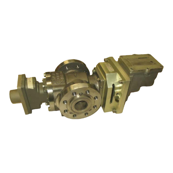
3171A Gas Valve The 3171A Gas Valve is a stainless steel valve capable of metering gas flow between 25 and 20 000 pph (11 and 9072 kg/h). The valve is designed to bolt into a 1 inch (25.4 mm) line by means of 0.625-11 UNC 2B tapped holes. The valve inlet and outlet flanges are class 600 per ANSI B16.5. -
Page 12: Em35Mr1 Actuator
EM35MR1/3171A Gas Valve Manual 26731 EM35MR1 Actuator The EM35MR1 actuator is an all-electric actuator designed for use in industrial gas turbine control applications. The EM35MR1 actuator consists of a high performance brushless servomotor and a precision planetary gearbox with two resolver-type shaft position sensors. -
Page 13: Chapter 2. Installation
Be careful when unpacking the EM 24 V Digital Driver and EM35MR1 actuator / 3171A gas valve. Check the devices for signs of damage such as bent or dented case and loose or broken parts. If damage is found, notify the shipper immediately. -
Page 14: Electrical Connections
Make sure that adequate room is allowed for required wiring and that the wiring and valve/actuator are accessible for service. There is an overboard drain port on the 3171A valve (see Figures 2-2 and 2-3). The drain is to be plumbed to an area outside the turbine enclosure. The drain vents the cavities between the inner and outer seals on both ends of the valve shaft. - Page 15 (Figure 2-5). Figure 2-5 is the plant wiring diagrams for the EM driver, EM35MR1 actuator/3171A gas valve when conduit is used for all wire runs. Consult the EM Driver manual (26159) for specific wiring requirements and procedures.
-
Page 16: Figure 2-1. Wago 264 Series Terminal Block
EM35MR1/3171A Gas Valve Manual 26731 2. The metering valve is not shipped with any field wiring attached (such as pigtails) but rather is provided with internal terminal blocks for field wiring. These terminal blocks are located under the explosion-proof covers on the actuator and resolver housings. -
Page 17: Figure 2-2A. Em35Mr1 Actuator/3171A Gas Valve/Resolver
Manual 26731 EM35MR1/3171A Gas Valve Figure 2-2a. EM35MR1 Actuator/3171A Gas Valve/Resolver (NPT electrical conduit entries) Woodward... -
Page 18: Figure 2-2B. Em35Mr1 Actuator/3171A Gas Valve/Resolver
EM35MR1/3171A Gas Valve Manual 26731 Figure 2-2b. EM35MR1 Actuator/3171A Gas Valve/Resolver (NPT electrical conduit entries) Woodward... -
Page 19: Figure 2-3A. Em35Mr1 Actuator/3171A Gas Valve Position Switch/Resolver
Manual 26731 EM35MR1/3171A Gas Valve Figure 2-3a. EM35MR1 Actuator/3171A Gas Valve Position Switch/Resolver (metric electrical conduit entries) Woodward... -
Page 20: Figure 2-3B. Em35Mr1 Actuator/3171A Gas Valve Position Switch/Resolver
EM35MR1/3171A Gas Valve Manual 26731 Figure 2-3b. EM35MR1 Actuator/3171A Gas Valve Position Switch/Resolver (metric electrical conduit entries) Woodward... -
Page 21: Figure 2-4. Dvp Driver Drawing
Manual 26731 EM35MR1/3171A Gas Valve Figure 2-4. DVP Driver Drawing Woodward... -
Page 22: Figure 2-5. Plant Wiring Diagram
EM35MR1/3171A Gas Valve Manual 26731 Figure 2-5. Plant Wiring Diagram Woodward... -
Page 23: Chapter 3. Description Of Operation
Manual 26731 EM35MR1/3171A Gas Valve Chapter 3. Description of Operation EM35MR1 Actuator The EM35MR1 electric actuator is comprised of a brushless dc motor, a clutch assembly, a gearhead assembly, and an explosion-proof housing. The brushless dc motor uses Samarium Cobalt permanent magnets bonded and sleeved to the rotor. -
Page 24: Water Ingress Protection
Turbine Water Wash Process—Some customers perform a water wash of the turbine compressor section which can result in incidental water spray directed onto the actuator. The EM35MR1/3171A valve assembly should be properly protected from this water spray. Conduit Fittings—Woodward recommends that rigid or flexible conduit be used to route the actuator wiring. -
Page 25: Chapter 4. Actuator/Valve Calibration
Failure to follow the procedure herein, or any non-Woodward alteration (including attempt to repair), or damage to the valve, may result in a change of characteristics leading to the same potential hazards. -
Page 26: Chapter 5. Troubleshooting
EM35MR1/3171A Gas Valve Manual 26731 Chapter 5. Troubleshooting General Faults in the governing system are usually revealed as speed variations of the prime mover, but it does not necessarily follow that such speed variations indicate governing system faults. Therefore, when improper speed variations appear, check all components including the prime mover for proper operation. - Page 27 Manual 26731 EM35MR1/3171A Gas Valve Procedure Locate the coupling assembly between the 3171A gas valve and the EM35 actuator; it can be viewed through the long vertical slot in the adapter housing. Adapter Housing EM35 Mounting Screws EM35 Actuator Coupling Access Slot Using the 3/16”...
- Page 28 EM35MR1/3171A Gas Valve Manual 26731 Using the 5/16” Allen wrench, remove the five socket head cap screws and lock washers that mount the EM35 actuator to the adapter housing. Remove the EM35 actuator from the assembly. Before installing the new EM35 actuator, properly orient the unit so the two lining pins for the actuator match up with the corresponding holes in the adapter housing.
-
Page 29: Chapter 6. Valve Sizing-Non-Dle Applications
Manual 26731 EM35MR1/3171A Gas Valve Chapter 6. Valve Sizing—Non-DLE Applications Determination of Effective Area In order to choose the proper size of valve for an application, the effective area required to meet your maximum flow requirement must first be determined. The effective area is determined using the following equations. -
Page 30: Valve Sizing And The Effective Area Tables
100 percent travel row for the applicable pressure ratio column. Woodward recommends that no less than 60% valve travel be used for the full control range. Using less than that could cause instability problems as the system attempts to control at very low increments of travel. -
Page 31: Determining The Demand Required To Achieve Specific Flows
Notes on the Valve Sizing and Application Program The algorithm used for sizing and demand value determination used in the standard valve application programs available for the 3171A is basically the same as that described above. However, the program makes use of a valve inlet pressure compensation algorithm that enhances the accuracy of the calculation. -
Page 32: Table 6-1. Effective Area Table (0.45 Port)
EM35MR1/3171A Gas Valve Manual 26731 Table 6-1. Effective Area Table (0.45 port) Valve angle = Resolver Feedback Angle – Resolve Offset Angle Resolver Offset Angle = ~20 degrees 4 mA = 0° valve angle = 0 % valve position = ~20° resolver angle min stop = –2 degrees valve angle... -
Page 33: Table 6-2. Effective Area Table (0.56 Port)
Manual 26731 EM35MR1/3171A Gas Valve Table 6-2. Effective Area Table (0.56 port) Valve angle = Resolver Feedback Angle – Resolve Offset Angle Resolver Offset Angle = ~20 degrees 4 mA = 0° valve angle = 0 % valve position = ~20° resolver angle min stop = –2 degrees valve angle... -
Page 34: Table 6-3. Effective Area Table (0.80 Port)
EM35MR1/3171A Gas Valve Manual 26731 Table 6-3. Effective Area Table (0.80 port) Valve angle = Resolver Feedback Angle – Resolve Offset Angle Resolver Offset Angle = ~20 degrees 4 mA = 0° valve angle = 0 % valve position = ~20° resolver angle min stop = –2 degrees valve angle... -
Page 35: Chapter 7. Maintenance
EM35MR1/3171A Gas Valve Chapter 7. Maintenance There are no critical maintenance items in the EM35MR1/3171A gas valve assemblies, such as filters that should be changed, etc. The valve assembly should be visually inspected, in accordance with your specific maintenance schedule. Each site must determine the appropriate schedule based on the severity of the service conditions. -
Page 36: Chapter 8. Service Options
Woodward systems and components for the retrofits and overhauls, long term service contracts, emergency repairs, etc. You can locate your nearest Woodward distributor, AISF, RER, or RTR on our website at: www.woodward.com/directory... -
Page 37: Woodward Factory Servicing Options
Flat Rate Remanufacture: Flat Rate Remanufacture is very similar to the Flat Rate Repair option with the exception that the unit will be returned to you in “like- new” condition and carry with it the full standard Woodward product warranty (Woodward Product and Service Warranty 5-01-1205). This option is applicable to mechanical products only. -
Page 38: Replacement Parts
Engineering Services Woodward offers various Engineering Services for our products. For these services, you can contact us by telephone, by email, or through the Woodward website. Technical Support ... -
Page 39: How To Contact Woodward
Manual 26731 EM35MR1/3171A Gas Valve How to Contact Woodward For assistance, call one of the following Woodward facilities to obtain the address and phone number of the facility nearest your location where you will be able to get information and service. -
Page 40: Em35Mr1/3171A Specifications
24 Vdc. This slew rate shall be measured using the speed achieved between the 10% and 90% points. The rated stroke of the 3171A Gas Valve is 45°. System bandwidth is nominally greater than 31.4 rad/s (5.0 Hz). The frequency response mimics a 2-pole linear system, with the bandwidth corresponding to –6 dB gain. -
Page 41: Revision History
Manual 26731 EM35MR1/3171A Gas Valve Revision History Changes in Revision D— Compliance Updates Updated Declarations Changes in Revision C— Added DVP Driver drawing (Figure 2-4) Changes in Revision B— Added Effective Area tables for 0.45, 0.56, and 0.80 ports at the end of Chapter 6. -
Page 42: Declarations
EM35MR1/3171A Gas Valve Manual 26731 Declarations Woodward... - Page 43 Manual 26731 EM35MR1/3171A Gas Valve Woodward...
-
Page 44: Em35Mr1/3171A Gas Valve Manual
EM35MR1/3171A Gas Valve Manual 26731 Woodward... - Page 45 Manual 26731 EM35MR1/3171A Gas Valve Woodward...
- Page 46 EM35MR1/3171A Gas Valve Manual 26731 Woodward...
- Page 47 26731 Please reference publication ËB26731è:èD´ ¹ ´ » µ ¸ Î PO Box 1519, Fort Collins CO 80522-1519, USA 1041 Woodward Way, Fort Collins CO 80524, USA Phone +1 (970) 482-5811 Email and Website—www.woodward.com Woodward has company-owned plants, subsidiaries, and branches, as well as authorized distributors and other authorized service and sales facilities throughout the world.
Need help?
Do you have a question about the 3171A and is the answer not in the manual?
Questions and answers