
Related Manuals for Campbell CR200


Summary of Contents for Campbell CR200
- Page 1 CR200/CR200X Series Dataloggers Revision: 6/11 C o p y r i g h t © 2 0 0 0 - 2 0 1 1 C a m p b e l l S c i e n t i f i c ,...
- Page 2 Campbell. Campbell will return such products by surface carrier prepaid within the continental United States of America. To all other locations, Campbell will return such products best way CIP ® (Port of Entry) INCOTERM 2010, prepaid.
-
Page 3: Table Of Contents
Table of Contents Section 1. Introduction ..........1 1.1 CR200(X) series Datalogger Models ..............1 Section 2. Quickstart Tutorial ........3 2.1 Primer - CR200(X) Data Acquisition..............3 2.1.1 Components of a Data Acquisition System ..........3 2.1.2 CR200(X) Mounting................. 4 2.1.3... - Page 4 Measurement and Control Peripherals..49 5.1 Control Output .....................49 5.1.1 Binary Control..................49 5.2 Other Peripherals....................51 5.2.1 TIMs......................51 Section 6. CR200(X) Power Supply ......53 6.1 Power Requirement ....................53 6.2 Calculating Power Consumption................53 6.3 Power Supplies.....................53 6.3.1 Battery Connection..................53 Section 7. Grounding ..........55 7.1 ESD Protection.....................55...
- Page 5 Table of Contents 9.7 Declarations II - Declared Sequences ..............77 9.7.1 Data Tables ..................... 77 9.7.2 Subroutines ..................... 83 9.8 Program Execution Timing .................. 83 9.9 Instructions......................84 9.9.1 Measurement and Data Storage Processing ..........84 9.9.2 Parameter Types ..................85 9.9.3 Names in Parameters ................
- Page 6 Table of Contents 11.4.3 SDI-12 Power Considerations...............118 11.5 Wind Vector .....................120 11.5.1 OutputOpt Parameters................120 11.5.2 Wind Vector Processing................120 11.6 TrigVar and DisableVar - Controlling Data Output and Output Processing ..125 11.7 Multiple Data Intervals in Data Tables.............126 Section 12. Memory and Data Storage ....129 12.1 Data Storage .....................129 12.1.1 Data Table Storage................129...
- Page 7 C.1 RS-232 Communications Port ................21 C.1.1 Pin-Out....................21 Appendix D. ASCII / ANSI Table......... 23 Appendix E. Antenna Usage and Compliance..27 E.1 Use of Antenna with CR200(X)................27 E.2 Part 15 FCC Compliance Warning ..............27 E.2.1 Use of Approved Antennas..............28...
- Page 8 Index ................35 List of Figures Figure 1: Data Acquisition System Components............3 Figure 2: CR200(X) Wiring Panel.................5 Figure 3: Analog Sensor Wired to Single-Ended Channel #1 ........6 Figure 4: Half Bridge Wiring -- Wind Vane Potentiometer ..........7 Figure 5: Pulse Input Types...................7 Figure 6: Pulse Input Wiring -- Anememeter Switch ............8...
- Page 9 Figure 52: Enclosure ....................148 Figure 53: Accuracy, Precision, and Resolution ..........Ap. 13 List of Tables Table 1. CR200 series Dataloggers with Built-In Radio ..........2 Table 2. PC200W EZSetup Wizard Example Selections........... 12 Table 3. Internal Lithium Battery Specifications ............34 Table 4.
- Page 10 Table 39. PakBus Leaf Node and Router Device Configuration......Ap. 33 Table 40. CR200(X) Telecommunications Options ..........Ap. 33 Table 41. Network Links available from Campbell Scientific ......Ap. 33 Table 42. Voltage Transient Suppressors available from Campbell Scientific ...Ap. 34 List of CRBasic Examples CRBASIC EXAMPLE 1. Inserting Comments............69 CRBASIC EXAMPLE 2.
-
Page 11: Section 1. Introduction
The limits of the CR200(X) are defined by our customers. Our intent with the CR200(X) manual is to guide you to the tools you need to explore the limits of your application. -
Page 12: Table 1. Cr200 Series Dataloggers With Built-In Radio
SAT HDR GOES satellite transmitter. While the CR295 required a special operating system, the CR295X does not. Note: Throughout this manual CR200(X) will be used to refer to all of the different models of datalogger in the CR200-series and CR200X-series. In the cases where information applies only to a specific model or series of datalogger, that will be clearly specified. -
Page 13: Section 2. Quickstart Tutorial
Quickstart tutorial gives a cursory look at CR200(X) data acquisition. Primer - CR200(X) Data Acquisition Data acquisition with the CR200(X) is the result of a step wise procedure involving the use of electronic sensor technology, the CR200(X), a telecommunications link, and PC datalogger support software. -
Page 14: Cr200(X) Mounting
Every measurement does not need to be stored. The CR200(X) will store data in memory awaiting transfer to the PC via external storage devices or telecommunications. -
Page 15: Battery Backup
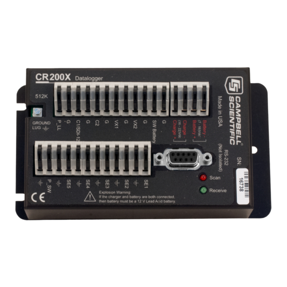
Section 2. Quickstart Tutorial Figure 2: CR200(X) Wiring Panel 2.1.4 Battery Backup A lithium battery backs up the CR200(X) clock, program, and memory if it loses power. 2.1.5 Power Supply The CR200(X) is powered by a nominal 12 volt DC source. Acceptable power range is 7 to 16 VDC. -
Page 16: Analog Sensors
Bridge Sensors Bridge sensors change resistance with respect to environmental change. Resistance is determined by measuring the difference between the excitation voltage supplied to the bridge and the voltage detected by the CR200(X) returning from the bridge. 2.1.8.1 Voltage Excitation The CR200(X) supplies a precise excitation voltage via excitation terminals. -
Page 17: Pulse Sensors
Figure 4: Half Bridge Wiring -- Wind Vane Potentiometer 2.1.9 Pulse Sensors The CR200(X) can measure switch closures, low-level AC signals (waveform breaks zero volts), or voltage pulses. Compatible signal types are illustrated in FIGURE. Pulse Input Types (p. 7). A pulse input wiring example is shown in FIGURE. -
Page 18: Digital I/O Ports
Figure 6: Pulse Input Wiring -- Anemometer Switch 2.1.10 Digital I/O Ports The CR200(X) has 2 digital I/O ports selectable, under program control, as binary inputs or control outputs. These are multi-function ports including: device driven interrupts, switch closure pulse counting, high frequency pulse counting, and SDI-12 communications. -
Page 19: Sensors
CRBASIC Help. Note: For the CR200, SerialInput () is a special instruction, which is available only in the special S operating system. -
Page 20: Hands-On Exercise - Measuring Temperature
Figure 8: Location of RS-232 Port Figure 9: Use of RS-232 when Reading RS-232 Devices Hands-on Exercise - Measuring Temperature This tutorial is designed to illustrate the function of the CR200(X). During the exercise, the following items will be described. •... -
Page 21: Hardware Setup
With Reference to FIGURE. Power and RS-232 Connections (p. 11). 1. Connect external power (7 – 16VDC) to the CR200 by inserting the positive lead into the "Battery +". 2. Insert the negative lead into the "Battery-". 3. Connect the RS-232 cable (PN 10873, provided) between the RS-232 port on the CR200(X) and the RS-232 port on the PC. -
Page 22: Table 2. Pc200W Ezsetup Wizard Example Selections
USB port. This will prevent data transfer between the software and CR200(X). Should this occur, simply move the USB cable back to the original port. If this is not possible, it will be necessary to close the PC200W software and open it a second time to refresh the available COM ports. -
Page 23: Figure 11: Pc200W Main Window
This portion of the tutorial will use Short Cut to create a program that measures air temperature (°C) with a 109 Temperature Probe, and rainfall (mm) with a TE525WS rain gage. The CR200(X) will take samples every ten seconds and store averages of these values at one minute intervals. -
Page 24: Figure 12: Short Cut Temperature Sensor Folder
Select New Program. 3. A drop-down list will appear showing different dataloggers. Select the CR200(X) and click OK. 4. The program will now ask for the scan interval. Set the interval to 10 seconds and click OK. -
Page 25: Figure 13: Short Cut Thermocoupler Wiring
1. Click on the Wiring Diagram link to view the sensor wiring diagram. Attach the 109 Temperature Probe and TE525 Rain Gauge to the CR200(X) as shown in the diagram. Click on Outputs to advance to the next step. Figure 14: Short Cut Wiring Diagram 2.2.3.1.5... -
Page 26: Figure 15: Short Cut Outputs Tab
Section 2. Quickstart Tutorial Figure 15: Short Cut Outputs Tab 2.2.3.1.6 Procedure (Short Cut Steps 12 –18) 1. By default, there are two Tables initially available. Both Tables have a Store Every field along with a drop-down box to select the time units. These are used to set the time interval when data is stored. -
Page 27: Figure 16: Short Cut Output Table Definition
Section 2. Quickstart Tutorial Figure 16: Short Cut Output Table Definition 2.2.3.1.7 Procedure (Short Cut Step 19) 1. Click on Finish to compile the program. Give the program the name "QuickStart." A prompt will ask if you want to send the program to the datalogger. -
Page 28: Figure 18: Pc200W Connect Button
Another window will open. Browse to the C:\CampbellSci\SCWin folder, select the QuickStart.CR2 file, and then click the Open button. A status bar will appear while the program is sent to the CR200(X) followed by a confirmation that the transfer was successful. Click OK to close this window. -
Page 29: Figure 19: Pc200W Monitor Data Tab
Section 2. Quickstart Tutorial Figure 19: PC200W Monitor Data Tab 2.2.3.2.3 Procedure (PC200W Step 5) 1. In the Add Selection window, click on the OneMin table, and then click Paste. The OneMin table is now displayed in the main display. Figure 20: PC200W Monitor Data Tab 2.2.3.2.4 Procedure (PC200W Step 6) -
Page 30: Figure 21: Pc200W Collect Data Tab
Section 2. Quickstart Tutorial Figure 21: PC200W Collect Data Tab 2.2.3.2.5 Procedure (PC200W Steps 7–9) 1. Click the OneMin box so a check mark appears in the box. Under the "What to Collect" heading, select "New data from datalogger." This selects which data will be collected. -
Page 31: Figure 23: Pc200W View Data Table
Section 2. Quickstart Tutorial 2.2.3.2.6 Procedure (PC200W Step 10) 1. Click on the Open File icon to open a file for viewing. Select the "CR200Series_OneMin.dat" file and click on Open. The collected data is now shown. Figure 23: PC200W View Data Table 2.2.3.2.7 Procedure (PC200W Step 11) 1. - Page 32 Section 2. Quickstart Tutorial...
-
Page 33: Section 3. Overview
(p. 24) illustrates a common CR200(X)-based data acquisition system. The CR200(X) is a multimeter with memory and timekeeping. It is one part of a data acquisition system. To acquire quality data, suitable sensors and reliable telecommunications devices are also required. -
Page 34: Programmed Instructions Are Evaluated Sequentially
Section 3. Overview Figure 25: Features of a Data Acquisition System 3.1.1 Programmed Instructions Are Evaluated Sequentially The CR200(X) evaluates programmed instructions sequentially. -
Page 35: Sensor Support
3.1.3 Input / Output Interface: The Wiring Panel The wiring panel of the CR200(X) is the interface to all CR200(X) functions. Most CR200(X) functions are best introduced by reviewing features of the CR200(X) wiring panel. FIGURE. CR200(X) Wiring Panel (p. - Page 36 Pulse count measurements use dedicated hardware -- pulse count accumulators, which are always monitoring the input signal, even when the CR200(X) is between program scans. In contrast, period average measurement instructions only monitor the input signal during a program scan.
- Page 37 38. • CR200(X) used as a PLC (programmable logic controller): Utilizing peripheral relays and analog output devices, the CR200(X) can manage binary and variable control devices through the following output channels: • Digital I/O: 2 channels (C1/C2) configurable for pulse output duration.
- Page 38 (Appendix p. 30) before connecting power. • Input voltages in excess of 18 V may damage the CR200 and/or power supply. Power to charge a 12 V lead-acid battery (16-22 VDC) must be connected to the Charge+ and Charge- terminals NOT to Battery+ and Battery-.
-
Page 39: Power Requirements
CR200(X) Power Supply (p. 53). The CR200(X) operates from a DC power supply with voltage ranging from 7 to 16 V, and is internally protected against accidental polarity reversal. The CR200(X) has modest input power requirements, typically an average current drain of less than 3 mA. -
Page 40: Memory And Data Storage
Support Software (p. 143)). OS files are sent to the CR200(X) with DevConfig or through the program Send button in datalogger support software. When the OS is sent via DevConfig, most settings are cleared, whereas, when sent via datalogger support software, most settings are retained. -
Page 41: Communications Overview
Section 3. Overview 512 kbytes in newer CR200s and in all CR200(X)s. CR200s with the increased memory have "512K" on their label. Figure 26: CR200(X) Wiring Panel 3.1.7 Communications Overview Read More! See Telecommunications and Data Retrieval (p. 131). The CR200(X) communicates with external devices to receive programs, send data, or act in concert with a network. -
Page 42: Maintenance Overview
CR200(X). Water can come from flooding or sprinkler irrigation, but most often comes as condensation. In most cases, protecting from water is as easy as placing the CR200(X) in a weather tight enclosure with desiccant and elevating the enclosure above the ground. The CR200(X) is shipped with desiccant to reduce humidity. -
Page 43: Scientific
The CR200(X) contains a lithium battery that operates the clock and SRAM when the CR200(X) is not powered. The CR200(X) does not draw power from the lithium battery while it is powered by an external source. In a CR200(X) stored at room temperature, the lithium battery should last approximately 5 years (less at temperature extremes). -
Page 44: Pc Support Software
PC200W Starter Software is available at no charge at www.campbellsci.com. It supports a transparent RS-232 connection between PC and CR200(X), and includes Short Cut for creating CR200(X) programs. Tools for setting the datalogger clock, sending programs, monitoring sensors, and on-site viewing and collection of data are also included. -
Page 45: Specifications
Section 3. Overview Specifications... - Page 46 Section 3. Overview...
-
Page 47: Section 4. Sensor Support
CR200(X) Power Supply (p. 53). The CR200(X) is a convenient router of power for sensors and peripherals requiring a 2.5, 5 or 12 VDC source. It has one program-controlled switched 12 Volt terminal (SW Battery), and two switched voltage excitation terminals (VX1, VX2). -
Page 48: Switched Unregulated (Nominal 12 Volt)
CR200(X) analog measurement error is calculated as Error = Gain Error (%) + Offset Error Gain error is expressed as ±% and is a function of input voltage and CR200(X) temperature. It is minimized by factory calibration and increases with component temperature and aging. - Page 49 Section 4. Sensor Support Note The accuracy specification includes only the CR200(X)’s contribution to measurement error. It does not include the error of sensors. For example, assume the following (see Specifications (p. 35)): • Input Voltage: +2000 mV • Programmed Measurement Instruction: VoltSE () •...
-
Page 50: Voltage Range
Section 4. Sensor Support Figure 27: Voltage Measurement Accuracy (0° to 40° C) 4.2.3 Voltage Range The CR200(X) has one analog voltage range of 0 to 2.5 volts. The resolution for a single A/D conversion is 0.6 millivolts. 4.2.4 Integration Integration is used to reduce the noise included in a measurement. -
Page 51: Self-Calibration
Two bridge measurement instructions are included in the CR200(X), ExDelSE () and Therm109 (). ExDelSE () is used with sensors that have a simple half bridge circuit. -
Page 52: Measurements Requiring Ac Excitation
FIGURE. Switch Closure Pulse Sensor p. 42 is a generalized schematic showing connection of a pulse sensor to the CR200(X). The CR200(X) features two dedicated pulse input channels, P_SW and P_LL, and two digital I/O channels, C1and C2, for measuring pulse output sensors. Activated by the PulseCount () instruction, dedicated 16-bit counters on P_SW, P_LL, C1 and C2 are used to accumulate all counts over the user specified scan interval. -
Page 53: Pulse Input Channels
Section 4. Sensor Support Note: The PulseCount () instruction should not be used in a conditional statement or subroutine. To ensure all pulses are detected, it must be executed each scan. Execution of PulseCount () within a scan involves determining the accumulated counts in each dedicated 16-bit counter since execution of the last PulseCount (). -
Page 54: Figure 30: Pulse Input Types
FIGURE. Pulse Input Types (p. 7) illustrates pulse input types measured by the CR200(X). Dedicated pulse input channel P_SW can be configured to read high- frequency pulses or switch closure, while P_LL can be configured to read a low-level AC signal. With a 100 kOhm pull-up resistor added to the wiring... -
Page 55: Pulse Input On Digital I/O Channels C1-C2
Low-level AC signals cannot be measured directly on channels C1 – C2. Period Averaging Measurements The CR200(X) can measure the period of a signal on any single-ended analog input channel (SE 1 - 5). The specified number of cycles are timed with a resolution of 70 ns, making the resolution of the period measurement 70 ns divided by the number of cycles chosen. -
Page 56: Recording
It is a simple protocol, requiring only a single communication wire. Typically, the data acquisition unit also supplies power (12V and ground) to the SDI-12 sensor. The CR200(X) is equipped with 1 SDI-12 channel and an SDI12Recorder () CRBASIC instruction. -
Page 57: Serial Sensors
Serial Sensors 4.7.3.1 SDI-12 Sensors The SDI-12 standard allows cable lengths of up to 200 feet. Campbell Scientific does not recommend SDI-12 sensor lead lengths greater than 200 feet; however, longer lead lengths can sometimes be accommodated by increasing the wire gage and/or powering the sensor with a second 12 vdc power supply placed near the sensor. - Page 58 Section 4. Sensor Support...
-
Page 59: Section 5. Measurement And Control Peripherals
Campbell Scientific applications engineer. Control Output Controlling power to an external device is a common function of the CR200(X). On-board control terminals are available for binary (on / off) control. Many devices are conveniently controlled with the SW Battery (Switched 12 Volt) terminal on the CR200(X). - Page 60 TABLE. Current Sourcing Limits (p. 38). A 12V switching circuit, driven by a digital I/O port, is also available from Campbell Scientific. Note The SW Battery supply is unregulated and can supply up to 900 mA at 20°C. See TABLE. Current Sourcing Limits (p.
-
Page 61: Other Peripherals
TIMs include voltage dividers for cutting the output voltage of sensors to voltage levels compatible with the CR200(X), modules for completion of resistive bridges, and shunt modules for measurement of analog current sensors. Refer to APPENDIX. - Page 62 Section 5. Measurement and Control Peripherals...
-
Page 63: Section 6. Cr200(X) Power Supply
Power Requirement The CR200(X) operates from a DC power supply with voltage ranging from 7 to 16 V. It is internally protected against accidental polarity reversal. Input voltages in excess of 18 V may damage the CR200(X) and/or power supply. - Page 64 For example, local effects such as mountain shadows, fog from valley inversion, snow, ice, leaves, birds, etc. shading the panel should be considered. If help is needed in determining system power requirements, contact Campbell Scientific's Marketing Department.
-
Page 65: Section 7. Grounding
Section 7. Grounding Grounding the CR200(X) and its peripheral devices and sensors is critical in all applications. Proper grounding will ensure the maximum ESD (electrostatic discharge) protection and higher measurement accuracy. ESD Protection ESD (electrostatic discharge) can originate from several sources, the most common, and most destructive, being primary and secondary lightning strikes. -
Page 66: Lightning Protection
Campbell Scientific has for many years employed a simple and inexpensive design that protects most systems in most circumstances. It is, however, not infallible. Note Lightning strikes may damage or destroy the CR200(X) and associated sensors and power supplies. In addition to protections discussed in ESD Protection (p. -
Page 67: Single-Ended Measurement Reference
Although the CR200(X) is not sensitive enough for low-level measurements and ground potential fluctuations are not usually a problem, the grounding scheme in the CR200(X) has been designed to eliminate ground potential fluctuations due to changing return currents from SW Battery, excitation channels, and the control ports. - Page 68 Section 7. Grounding Examples: • Connect grounds associated with SW Battery, VX1 (EX1), VX2 (EX2), C1, and C2 to G terminals. • Connect the low side of single-ended sensors to the nearest ( ) terminal on the analog input terminal blocks. •...
-
Page 69: Section 8. Cr200(X) Configuration
Connections p. 11. DevConfig DevConfig (Device Configuration Utility) is the preferred tool for configuring the CR200(X). It is made available as part of LoggerNet, PC400, and at www.campbellsci.com. Features of DevConfig include: • Communicates with devices via direct RS-232 only. -
Page 70: Sending The Operating System
CR200(X). Since sending an OS to the CR200(X) resets memory, data loss will certainly occur. Depending on several factors, the CR200(X) may also become incapacitated for a time. Consider the following before updating the OS. - Page 71 CR200(X). When the Start button is clicked, DevConfig offers a file open dialog box that prompts for the operating system file (*.obj file). When the CR200(X) is powered-up, DevConfig starts to send the operating system. When the operating system has been sent, a confirming message dialog box.
-
Page 72: Settings
Settings 8.3.1 Settings via DevConfig The CR200(X) has a number of properties, referred to as "settings", some of which are specific to the PakBus® communications protocol. Read More! PakBus® is discussed in PakBus® Overview (p. 133) and the PakBus®... - Page 73 63) that gives the user a chance to save and print the settings for the device. Figure 41: Summary of CR200(X) Configuration Clicking the Factory Defaults button on the Settings Editor will send a command to the device to revert to its factory default settings. The reverted values will not take effect until the final changes have been applied.
- Page 74 Setting Editor tab and the Status table. The CR200(X) default PakBus address is 1. Unless the CR200(X) is used in a network, there may be no need to change the PakBus address or any other default setting.
- Page 75 • Power Mode specifies the power wait state that will be set in the built-in radio and how much power the CR200(X) radio consumes from its power supply. This value should be consistent with the RF400 series base station used to communicate with the CR200(X).
-
Page 76: Settings Via Crbasic
CR200(X), the remedy for which may be a site visit. 8.3.3 Settings via Terminal Emulator The CR200(X) has a simple terminal interface that can be accessed with a PC running a terminal emulator such as those available in PC200, PC400, or LoggerNet. -
Page 77: Durable Settings
Section 8. CR200(X) Configuration The CR200(X) will time out and exit the terminal mode if it does not receive a command within 12 seconds. Enter a command by pressing the command followed by the carriage return. The commands are: Commands Action (what returns) Trap Code 16 Information "OK"... - Page 78 Section 8. CR200(X) Configuration...
-
Page 79: Section 9. Programming
('). Comments can be entered either as independent lines or following CR200(X) code. When the CR200(X) compiler sees a single quote ('), it ignores the rest of the line. -
Page 80: Short Cut Editor And Program Generator
All-purpose Symbolic Instruction Code) computer language, CRBASIC (Campbell Recorder BASIC). CRBASIC Editor is a text editor that facilitates creation and modification of the ASCII text file that constitutes the CR200(X) application program. CRBASIC Editor is available as part of LoggerNet / PC400 / RTDAQ datalogger support software packages. -
Page 81: Numerical Formats
10 numbers. Scientific notation, binary, and hexadecimal formats may also be used, as shown in TABLE. Formats for Entering Numbers in CRBASIC 71). Only standard base 10 notation is supported by Campbell Scientific hardware and software displays. Table 5. Formats for Entering Numbers in CRBASIC... -
Page 82: Structure
Define Aliases Assign aliases to variables. Define Units Assign engineering units to variable (optional). Units are strictly for documentation. The CR200(X) makes no use of Units nor checks Unit accuracy. Define data tables. Define stored data tables Process/store trigger Set triggers when data should be stored. -
Page 83: Declarations I - Single-Line Declarations
Public or Dim at the discretion of the programmer. Public variables can be viewed through software numeric monitors. Dim variables cannot. Up to 128 public variables can be declared in a CR200(X) program and up to 48 public variables declared in a CR200 program. - Page 84 Section 9. Programming Variable names can be up to 16 characters in length, but most variables should be no more than 12 characters long. This allows for the 4 additional characters that are added as a suffix to the variable name when it is output to a data table. Variable names cannot start with a number or contain spaces or quote marks (“), but can contain numbers and underscores (_).
-
Page 85: Crbasic Example 4. Using A Variable Array In Calculations
"Flag" works best because datalogger support software automatically adds variables call "Flag" to the Ports and Flags window. Because the CR200(X) does not support the Boolean data type, the IIF function may be used to distinguish between zero and non-zero values, effectively creating a Boolean value. -
Page 86: Constants
Section 9. Programming CRBASIC EXAMPLE 5. Flag Declaration and Use Public batt_volt Public Flag BeginProg Scan (1,Sec) Flag = IIF (Flag=0,0,-1) If Flag = true Then Battery (batt_volt) EndIf NextScan EndProg 9.6.2 Constants CRBASIC EXAMPLE. Using the Const Declaration (p. 76) shows use of the constant declaration. -
Page 87: Alias And Unit Declarations
Section 9. Programming TABLE. Predefined Constants and Reserved Words (p. 77) lists predefined constants. Table 7. Predefined Constants and Reserved Words Case FALSE Msec mv2500 mv5000 PROG SCAN Select TABLE TRUE Usec Until While 9.6.3 Alias and Unit Declarations A variable can be assigned a second name, or alias, by which it can be called throughout the program. -
Page 88: Table 8. Toa5 Environment Line
The trigger that initiates data storage is tripped either by the CR200(X)'s clock, or by an event, such as a high temperature. Up to 8 data tables can be created by the program for a CR200(X) (4 data tables for a CR200). -
Page 89: Table 9. Typical Data Table
(data line) number. Read More! See TABLE. Abbreviations of Names of Data Processes (p. 90) for a list of default field names. Table 9. Typical Data Table TOA5 CR200(X) CR2xx No_SN CR200(X).Std.01 Data.CR2 4098 OneMin... -
Page 90: Crbasic Example 8. Definition And Use Of A Data Table
Section 9. Programming CRBASIC EXAMPLE 8. Definition and Use of a Data Table 'Declare Variables Public Batt_Volt Public T109_C(2) 'Define Units Units Batt_Volt=Volts Units T109_C(2)=Deg C 'Define Data Tables DataTable (OneMin,True,-1) DataInterval (0,1,Min) Average (1,Batt_Volt,False) Average (2,T109_C(1),False) EndTable DataTable (Table1,True,-1) DataInterval (0,1440,Min) Minimum (1,Batt_Volt,False,False) EndTable... -
Page 91: Output Processing Instructions
Auto allocation is preferred in most applications since the CR200(X) sizes all tables such that they fill (and begin overwriting the oldest data) at about the same time. Approximately 2K bytes of extra data... -
Page 92: Crbasic Example 9. Use Of The Disable Variable
Section 9. Programming Consider the Average () instruction as an example of output processing instructions. Average () stores the average of a variable over the data storage output interval. Its parameters are: • Reps-number of elements in the variable array for which to calculate averages. -
Page 93: Subroutines
EndProg Program Execution Timing CR200(X) programs are built within a Scan () / NextScan structure, with only variable and data table declarations outside the Scan () / NextScan structure. In these programs, Scan () / NextScan creates an infinite loop, each periodic pass through the loop being synchronized to the CR200(X) clock. -
Page 94: Instructions
Measurement and Data Storage Processing CRBASIC instructions have been created for making measurements and storing data. Measurement instructions set up CR200(X) hardware to make measurements and store results in variables. Data storage instructions process measurements into averages, maxima, minima, standard deviation, FFT, etc. -
Page 95: Parameter Types
Section 9. Programming 9.9.2 Parameter Types Many instructions have parameters that allow different types of inputs. Common input type prompts are listed below. Allowed input types are specifically identified in the description of each instruction in CRBASIC Editor Help. • Constant, or Expression that evaluates as a constant •... -
Page 96: Expressions In Parameters
Section 9. Programming 9.9.4 Expressions in Parameters Read More! See Expressions (p. 87) for more information on expressions. Many parameters allow the entry of expressions. If an expression is a comparison, it will return -1 if the comparison is true and 0 if it is false (Logical Expressions (p. -
Page 97: Expressions
Floating point arithmetic is common in many electronic computational systems, but it has pitfalls high-level programmers should be aware of. Several sources discuss floating point arithmetic thoroughly. One readily available source is the topic "Floating Point" at Wikipedia.org. In summary, CR200(X) programmers should consider at least the following: •... -
Page 98: Logical Expressions
AND / OR operators are the same for logical statements and binary bitwise comparisons. In the binary number system internal to the CR200(X), "-1" is expressed with all bits equal to 1 (11111111). "0" has all bits equal to 0 (00000000). -
Page 99: Table 11. Logical Expression Examples
If X >= 5 then Y = 0 Sets the variable Y to 0 if the expression "X >= 5" is true, i.e. if X is greater than or equal to 5. The CR200(X) evaluates the expression (X >= 5) and registers in system memory a -1 if the expression is true, or a 0 if the expression is false. -
Page 100: Program Access To Data Tables
Section 9. Programming 9.11 Program Access to Data Tables CRBASIC has syntax provisions facilitating access to data in tables or information relating to a table. The syntax is entered directly into the CRBASIC program through a variable name. The general form is: "TableName.FieldName_Prc (Fieldname Index, Records Back)". - Page 101 Section 9. Programming Five special variable names are used to access information about a table: • FieldName • Output • Record • TableSize • TimeStamp Consult CRBASIC Editor Help Index topic "DataTable access" for complete information.
- Page 102 Section 9. Programming...
-
Page 103: Section 10. Crbasic Programming Instructions
PC400 / RTDAQ. Select instructions are explained more fully, some with example code, in Programming Resource Library (p. 109). Example code is throughout the CR200(X) manual. Refer to the table of contents Example index. 10.1 Program Declarations 10.1.1 Variable Declarations & Modifiers Alias Assigns a second name to a variable. -
Page 104: Data Table Declarations
Section 10. CRBASIC Programming Instructions 10.2 Data Table Declarations DataTable … EndTable Mark the beginning and end of a data table. Syntax DataTable (Name, TrigVar, Size) [data table modifiers] [on-line storage destinations] [output processing instructions] EndTable 10.2.1 Data Table Modifiers DataInterval Sets the time interval for an output table. -
Page 105: Single Execution At Compile
Section 10. CRBASIC Programming Instructions StdDev Calculates the standard deviation over the output interval. Syntax StdDev (Reps, Source, DisableVar) Totalize Sums the total over the output interval. Syntax Totalize (Reps, Source, DisableVar) 10.2.2.2 Multiple-Source Stores evapotranspiration (ETo) and other meteorological data. Most suitable for output intervals of less than 24 hours. -
Page 106: Program Control Instructions
Section 10. CRBASIC Programming Instructions 10.4 Program Control Instructions 10.4.1 Common Controls BeginProg … EndProg Mark the beginning and end of a program. Syntax BeginProg Program Code EndProg Call Transfers program control from the main program to a subroutine. Syntax Call subname CallTable Calls a data table, typically for output processing. - Page 107 Select Case … Case … Case Is … Case Else … EndSelect Executes one of several statement blocks depending on the value of an expression. CaseElse is optional. (EndSelect and EndIf call the same CR200(X) function). Syntax Select Case testexpression...
-
Page 108: Measurement Instructions
Allowable excitation voltages are +2500mV and +5000mV. Syntax ExDelSE (Dest, Reps, SEChan, ExChan, ExmV, Delay, Mult, Offset) Therm109 Measures a Campbell Scientific 109 thermistor Syntax Therm109 (Dest, Reps, SEChan, Vx/ExChan, SettlingTime, Integ, Mult, Offset) 10.5.3 Pulse Read More! See Pulse Count Measurement (p. -
Page 109: Digital I/O
Section 10. CRBASIC Programming Instructions PulseCount Measures number or frequency of voltages pulses on a pulse channel. Syntax PulseCount (Dest, PChan, PConfig, POption, Mult, Offset) 10.5.4 Digital I/O AnalogPortGet Configures an analog port as a digital input and stores the status of the input in a variable. -
Page 110: Processing And Math Instructions
Section 10. CRBASIC Programming Instructions SDI12SensorResponse Holds the source of the data to send to the SDI12 recorder. Syntax SDI12SensorSetup (Repetitions, SDIPort, SDIAddress, ResponseTime) SDI12SensorResponse (SDI12Source) 10.6 Processing and Math Instructions 10.6.1 Mathematical Operators ^ Raise to Power. * Multiply Divide + Add Subtract... -
Page 111: Trigonometric Functions
Section 10. CRBASIC Programming Instructions Used to perform a logical disjunction on two expressions. Syntax result = expr1 OR expr2 Performs a logical exclusion on two expressions. Syntax result = expr1 XOR expr2 10.6.3 Trigonometric Functions 10.6.3.1 Derived Functions TABLE. Derived Trigonometric Functions (p. -
Page 112: Arithmetic Functions
Section 10. CRBASIC Programming Instructions ASIN The ASIN function returns the arc sin of a number. Syntax x = ASIN(source) Returns the arctangent of a number. Syntax x = ATN(source) ATN2 Returns the arctangent of y / x. Syntax x = ATN(y , x) Returns the cosine of an angle specified in radians. -
Page 113: Spatial Processing
Section 10. CRBASIC Programming Instructions Returns the natural logarithm of a number. Ln and Log perform the same function. Syntax x = LOG(source) x = LN(source) Note LOGN = LOG(X) / LOG(N) LOG10 The LOG10 function returns the base 10 logarithm of a number. Syntax x = LOG10 (number) Divides two numbers and returns only the remainder. -
Page 114: Other Functions
Section 10. CRBASIC Programming Instructions MinSpa Finds the minimum value in an array. Syntax MinSpa (Dest, Swath, Source) RMSSpa Computes the RMS (root mean square) value of an array. Syntax RMSSpa (Dest, Swath, Source) StdDevSpa Used to find the standard deviation of an array. Syntax StdDevSpa (Dest, Swath, Source) 10.6.6... -
Page 115: Serial Input / Output
Sends the values from program variables or other characters out through a communications port. Syntax Print (PrintPort, PrintBaud, PrintParams) SerialInput Reads a serial sensor connected to the CR200(X)'s RS232 port. Syntax SerialInput (Dest, Max_Values, Termination_Char, FilterString) 10.9 Peer-to-Peer PakBus Communications... -
Page 116: Data Table Access And Management
'S' operating system, version 5.10 and greater (V06S). SendGetData Sends an array of values from a remote CR200(X) to a host datalogger and/or retrieves an array of data from the host datalogger. Syntax SendGetData(ResponseDest, Control, Measurement,... -
Page 117: Scada
(p. 139). Note: These instructions are supported only in a special operating system version 'M' for CR200 series dataloggers. That operating system must be loaded on the datalogger and the program compiled with the matching compiler to use ModBusMaster and ModBusSlave. No special operating system is required for CR200(X) series dataloggers. -
Page 118: Satellite Systems Programming
Instructions for GOES. Refer to satellite transmitter manuals available at www.campbellsci.com. 10.12.1 GOES The CR295 and CR295X dataloggers support communication through Campbell Scientific’s TX312 or HDR GOES satellite transmitters. The CR295(X) has an extra 9-pin serial port. The CR295 requires a special operating system and does not support radio telemetry or calculation of evapotranspiration and is not CE compliant. -
Page 119: Section 11. Programming Resource Library
Library 11.1 Remote Sensor Interface The CR200(X) is frequently used as a remote sensor interface for a “Host” datalogger. Typically, the host datalogger and the sensor(s) (CR200(X)) will have programs that will enable the sensors to operate with the minimum quiescent current drain (110 µa). -
Page 120: Radio Power Minimization
Thereafter, the CR200 calls at the appointed time slot. 11.2 Radio Power Minimization Power settings on the CR200(X) radio are used to optimize the current drain of the system. The radio can be set to be always on, power up once a second or every 8 seconds, or be turned on by the CR200(X) program. -
Page 121: Crbasic Example 17. Crbasic Example. Radio Power Minimization Program Examples
Units Period_uS()=uSec Units T109_C=Deg C DataTable(VWC_pin,True,-1) DataInterval(0,60,Min) Average(5,TxData(),False) Minimum (1,Batt_Volt,False,0) EndTable BeginProg SetStatus (RfPwrMode,RFpinEn) 'Configure CR200(X) power mode to pin enabled Scan(1,sec) If IfTime (0,15,Min) Then 'Take readings every 15 minutes Battery(Batt_Volt) Therm109(T109_C,1,5,1,1.0,0.0) SWBatt (1 ) 'Power CS625 sensors up PeriodAvg(Period_uS(1),1,0,100,10,1,1,0) -
Page 122: Multiple Switch Closure Measurements
2 (Switch Closure), while P_LL must use option 0 (Pulse Input). CRBASIC EXAMPLE 18. CRBASIC EXAMPLE. Two Rain Gages on a CR200(X) 'Rain(1) is wired to P_SW and Ground 'Rain(2) is wired to P_LL and Ground with a... -
Page 123: Table 14. Standard Sdi-12 Command & Response Set
Section 11. Programming Resource Library SDI-12 commands and responses are defined by the SDI-12 Support Group (www.sdi-12.org) and are summarized in TABLE. Standard SDI-12 Command & Response Set (p. 113). Sensor manufacturers determine which commands to support. The most common commands are detailed below. Table 14. - Page 124 Section 11. Programming Resource Library 11.4.1.1 Addressing A single probe should be connected to an SDI-12 input when using these commands. 11.4.1.1.1 Address Query Command (?!) Command ?! requests the address of the connected sensor. The sensor replies to the query with the address, a. 11.4.1.1.2 Change Address Command (aAb!) Sensor address is changed with command aAb!, where a is the current address...
- Page 125 11.4.1.2.2 Start Concurrent Measurement Command (aC!) Concurrent measurement allows the CR200(X) to request a measurement, continue program execution, and pick up the requested data on the next pass through the program. The datalogger scan rate should be set such that the resulting skew between time of measurement and time of data collection does not compromise data integrity.
-
Page 126: Communications
If a sensor cannot perform continuous measurements, then it responds to aRv! with the sensor address. 11.4.2 SDI-12 Communications The CR200(X) supports SDI-12 communication through two modes – transparent mode and programmed mode. • Transparent mode facilitates sensor set-up and troubleshooting. It allows commands to be manually issued and the full sensor response viewed. - Page 127 For example, when the SDI12Recorder() instruction is programmed with the M! command (note that SDI-12 address is a separate parameter), the CR200(X) issues the aM! AND aD0! commands with proper elapsed time between the two. The CR200(X) automatically issues retries as well as other services designed to make the SDI- 12 measurement work as trouble free as possible.
-
Page 128: Power Considerations
Section 11. Programming Resource Library SDIRecorder () Instruction SDICommand Entry Actions Internal to CR200(X) and Sensor CR200(X) : Issues aMv! command Sensor : Responds with atttnn CR200(X) : Waits until ttt seconds. Issues aDv! command(s) Sensor : Responds with data. -
Page 129: Table 15. Example Power Usage Profile For A Network Of Sdi-12 Probes
Section 11. Programming Resource Library will respond, however, all other probes will remain active until the timeout period expires. Example: Probe: Water Content Power Usage: • Quiescent: 0.25 mA • Measurement: 120 mA • Measurement Time: 15 s • Active: 66 mA •... -
Page 130: Wind Vector
WVc(1):Resultant Mean horizontal wind speed (Ū) WVc(2): Resultant mean wind direction (Θu) WVc(3): Standard deviation of wind direction σ(Θu). This standard deviation is calculated using Campbell Scientific's wind speed weighted algorithm. Use of the resultant mean horizontal wind direction is not recommended for straight-line Gaussian dispersion models, but may be used to model transport direction in a variable-trajectory model. - Page 131 Section 11. Programming Resource Library Note Cup anemometers typically have a mechanical offset which is added to each measurement. A numeric offset is usually encoded in the CRBASIC program to compensate for the mechanical offset. When this is done, a measurement will equal the offset only when wind speed is zero;...
- Page 132 Section 11. Programming Resource Library Scalar mean horizontal wind speed, S: where in the case of orthogonal sensors: Unit vector mean wind direction, where or, in the case of orthogonal sensors where Standard deviation of wind direction (Yamartino algorithm) where, and Ux and Uy are as defined above.
- Page 133 Figure 46: Mean Wind Vector where for polar sensors: or, in the case of orthogonal sensors: Resultant mean wind direction, Θu: Standard deviation of wind direction, σ (Θu), using Campbell Scientific algorithm: The algorithm for σ (Θu) is developed by noting (FIGURE. Standard Deviation of Direction (p.
- Page 134 Section 11. Programming Resource Library where Figure 47: Standard Deviation of Direction The Taylor Series for the Cosine function, truncated after 2 terms is: For deviations less than 40 degrees, the error in this approximation is less than 1%. At deviations of 60 degrees, the error is 10%. The speed sample can be expressed as the deviation about the mean speed, Equating the two expressions for Cos (θ') and using the previous equation for s Solving for (Θ...
-
Page 135: Trigvar And Disablevar - Controlling Data Output And Output Processing
Section 11. Programming Resource Library Resources Laboratory, NOAA, Idaho Falls, ID; and MERDI, Butte, MT. In these tests, the maximum differences in have never been greater than a few degrees. The final form is arrived at by converting from radians to degrees (57.296 degrees/radian). -
Page 136: Multiple Data Intervals In Data Tables
Section 11. Programming Resource Library CRBASIC EXAMPLE. Using TrigVar to Trigger Data Storage (p. 126) lists CRBASIC code that uses TrigVar () rather than DataInterval () to trigger data storage. FIGURE. Data from TrigVar Program (p. 126) shows data produced by the example code. -
Page 137: Crbasic Example 20. Crbasic Example. Programming For Two Data Intervals In One Data Table
Section 11. Programming Resource Library Time instructions in the TrigVar parameter of the DataTable declaration. Since DataInterval is not used, the table size cannot be autoallocated and table size should be carefully considered before being set to a specific number of records. CRBASIC EXAMPLE 20. - Page 138 Section 11. Programming Resource Library...
-
Page 139: Section 12. Memory And Data Storage
73). The DataTable () instruction allows the user to set the size of the data table. The maximum number of tables that can be created by the program is 4 for CR200 series dataloggers and 8 for CR200(X) series dataloggers. -
Page 140: Memory Conservation
Three features are available for complete or selective reset of CR200(X) memory. 12.3.1 Full Memory Reset Full memory reset occurs when an operating system is sent to the CR200(X) using DevConfig. A full memory reset does the following: • Clears and Formats CPU: drive (all program files erased) •... -
Page 141: Section 13. Telecommunications And Data Retrieval
For example, a common way to communicate with the CR200(X) is with PC200W software by way of a PC COM port. In this example, hardware are the PC COM port, the CR200(X) RS-232 port, and a serial cable. -
Page 142: Protocols
13.4.2 Data Format on Computer CR200(X) data stored on a PC via support software is formatted as either ASCII or Binary depending on the file type selected in the support software. Consult the software manual for details on the various available data file formats. -
Page 143: Section 14. Pakbus Overview
Devices, such as PCs, with addresses greater than 4000 are given special administrative access to the network PakBus addresses are set using DevConfig, PakBusGraph, or the CR200(X) status table. DevConfig (Device Configuration Utility) is the primary settings editor for Campbell Scientific equipment. It requires a hardwire RS-232 connection to a PC and allows backup of settings on the PC hard drive. -
Page 144: Router And Leaf Node Configuration
PC running LoggerNet is typically a central router. • Routers can be router-capable dataloggers or communications devices. The CR200(X) is always a leaf node. It cannot be configured as a router. The network shown in FIGURE. PakBus Network Addressing (p. 134) contains 6 routers and 8 leaf nodes. -
Page 145: Hello-Message (Two-Way Exchange)
Section 14. PakBus Overview 14.4.1 Hello-message (two-way exchange) A hello-message is an interchange between two nodes that negotiates a neighbor link. A hello-message is sent out in response to one or both of either a beacon or a hello-request. 14.4.2 Beacon (one-way broadcast) A beacon is a broadcast sent by a node at a specified interval telling all nodes within hearing that a hello-message can be sent. -
Page 146: Maintaining Links
Section 14. PakBus Overview 14.4.6 Maintaining Links Links are maintained by means of the CVI (communications verification interval). The CVI can be specified in each node with DevConfig. The following rules apply: • If Verify Interval = 0, then CVI = 2.5 x beacon interval* •... -
Page 147: Ping
14.5.1.1 Automatic Packet Size Adjustment The BMP5 file receive transaction allows the BMP5 client (LoggerNet) to specify the size of the next fragment of the file that the CR200(X) sends. Note The file receive transaction is used to get table definitions from the datalogger. -
Page 148: Traffic Flow
Section 14. PakBus Overview 14.5.3 Traffic Flow Keep beacon intervals as long as possible with higher traffic (large numbers of nodes and / or frequent data collection). Long beacon intervals minimize collisions with other packets and resulting retries. The minimum recommended beacon interval is 60 seconds. -
Page 149: Section 15. Alternate Telecoms Resource Library
RTU and ASCII. However, CR200(X)s communicate in RTU mode exclusively. Field instruments can be queried by the CR200(X). Because Modbus has a set command structure, programming the CR200(X) to get data from field instruments is much simpler than from serial sensors. Because Modbus uses a common bus and addresses each node, field instruments are effectively multiplexed to a CR200(X) without additional hardware. -
Page 150: Programming For Modbus
TABLE. CRBASIC Ports, Flags, Variables and Modbus Registers (p. 141) shows the linkage between CR200(X) ports, flags and Boolean variables and Modbus registers. Modbus does not distinguish between CR200(X) ports, flags, or Boolean variables. By declaring only ports, or flags, or Boolean variables, the declared feature is addressed by default. -
Page 151: Table 20. Crbasic Ports, Flags, Variables And Modbus Registers
Public ArrayV(20)* 40001 to 40041* 30001 to 30041* *Because of byte number differences, each CR200(X) domain variable translates to two Modbus domain input / holding registers. 15.1.3.2 CRBASIC Instructions - Modbus Complete descriptions and options of commands are available in CRBASIC Editor Help. -
Page 152: Troubleshooting
This can be true for either floating point, or integer formats. While other CRBasic dataloggers, such as the CR1000, can use the MoveBytes() instruction to output reverse byte order words, the CR200(X) does not have that capability. If reverse byte order words are required, either the master has to make an adjustment, which is sometimes possible, or the CR200(X) needs to replaced with a datalogger that supports the MoveBytes() instruction. -
Page 153: Section 16. Support Software
Network Planner, which assists in the configuration of networks. 16.1 Short Cut Short Cut utilizes an intuitive user interface to create CR200(X) program code for common measurement applications. It presents lists from which sensors, engineering units, and data output formats are selected. It supports by name most sensors sold by Campbell Scientific. -
Page 154: Pc400
Section 16. Support Software 16.4 PC400 PC400 is a mid-level software suite. It includes CRBASIC Editor, point-to-point communications over several communications protocols, simple real-time digital and graphical monitors, and report generation. It does not support scheduled collection or multi-mode communication networks. 16.5 RTDAQ RTDAQ is targeted for industrial and other high-speed data acquisition applications. -
Page 155: Pda Software
16.7 PDA Software PConnect Software supports PDAs with Palm Operating Systems. PConnectCE supports Windows Mobile and Pocket PC PDAs. Both support direct RS-232 connection to the CR200(X) for sending programs, collecting data, and digital real-time monitoring. 16.8 Network Planner Network Planner is a "drag and drop" application used in designing PakBus datalogger networks. - Page 156 Section 16. Support Software...
-
Page 157: Section 17. Care And Maintenance
Contact Campbell Scientific to obtain an RMA prior to shipping the CR200(X). 17.1 Temperature Range The CR200(X) is designed to operate reliably from -40ºC to +50°C in non- condensing environments. 17.2 Moisture Protection When humidity tolerances are exceeded and condensation occurs, damage to IC chips, microprocessor failure, and/or measurement inaccuracies due to condensation on the various PC board runners may result. -
Page 158: Replacing The Internal Battery
The CR200(X) contains a lithium battery that operates the clock and SRAM when the CR200(X) is not powered. The CR200(X) does not draw power from the lithium battery while it is powered by an external source. In a CR200(X) stored at room temperature, the lithium battery should last approximately 5 years (less at temperature extremes). -
Page 159: Table 23. Internal Lithium Battery Specifications
Section 17. Care and Maintenance A replacement lithium battery can be purchased from Campbell (part number 15598). TABLE. CR200(X) Lithium Battery Specifications p. 33 lists the specifications of the battery. However, Campbell Scientific recommends that the battery be replaced at the factory. - Page 160 Section 17. Care and Maintenance...
-
Page 161: Section 18. Troubleshooting
Skipped scans may compromise frequency measurements made with pulse channels. The error occurs because counts from a scan and subsequent skipped scans are regarded by the CR200(X) as having occurred during a single scan. The measured frequency can be much higher than actual. -
Page 162: Table 24. Program Download Errors
EEPROM memory failure. When this occurs the datalogger stops running its program and the red LED flashes twice per scan interval. The datalogger must be returned to CSI to replace the Serial Flash EEPROM. Contact a Campbell Scientific applications engineer to receive an RMA number. -
Page 163: Nan And ±Inf
18.1.2.1.1 Voltage Measurements The CR200(X) measures voltage inputs ranging from 0 to 2500 mV. Input signals that exceed this ranges result in an over range indicated by a NAN for the measured result. A voltage input not connected to a sensor is floating and the resulting measured voltage often remains near the voltage of the previous measurement. -
Page 164: Communications
18.2.2 Communicating with Multiple PC Programs A common practice is to monitor the performance of a CR200(X) using Devconfig or LoggerNet while the CR200(X) has an open connection to another copy of LoggerNet. For example, the main connection can be via RF while the performance monitoring is done via RS-232 port. -
Page 165: Power Supply
Power Supply product literature or Application Note. 18.3.2 Troubleshooting at a Glance Symptoms: Possible symptoms include the CR200(X) program not executing; WatchDogCnt in the Status table displaying a non-zero number. Affected Equipment: Batteries, charger/regulators, solar panels, transformers Likely Cause: Batteries may need to be replaced or recharged;... -
Page 166: Diagnosis And Fix Procedures
Section 18. Troubleshooting 18.3.3 Diagnosis and Fix Procedures 18.3.3.1 Battery Voltage Test... - Page 167 Section 18. Troubleshooting 18.3.3.2 Charging Circuit Test - Solar Panel...
- Page 168 Section 18. Troubleshooting 18.3.3.3 Charging Circuit Test - Transformer...
- Page 169 Section 18. Troubleshooting 18.3.3.4 Adjusting Charging Circuit Voltage...
- Page 170 Section 18. Troubleshooting...
-
Page 171: Appendix A. Glossary
Appendix A. Glossary A.1 Terms (Appendix p. 12). Analog-to-digital conversion. The process that translates analog voltage levels to digital values. accuracy A measure of the correctness of a measurement. See also Accuracy, Precision, and Resolution (Appendix p. 13). Amperes (Amps) Base unit for electric current. - Page 172 The software process of converting a human readable program to binary machine code. CR200(X) programs are compiled by the CRBASIC Editor. constant A packet of CR200(X) memory given an alpha-numeric name and assigned a fixed number. control I/O Terminals C1 - C2 or processes utilizing these terminals.
- Page 173 See VDC. Data communications equipment. While the term has much wider meaning, in the limited context of practical use with the CR200(X), it denotes the pin configuration, gender and function of an RS-232 port. The RS-232 port on the CR200(X) and on many 3 party telecommunications devices, such as a digital cellular modems, are DCE.
- Page 174 - even a few meters away - may be different. engineering units Units that explicitly describe phenomena, as opposed to the CR200(X) measurement units of millivolts or counts. Electrostatic discharge Environmental Sensor Station excitation Application of a precise voltage, usually to a resistive bridge circuit.
- Page 175 Appendix A. Glossary Hello Exchange The process of verifying a node as a neighbor. Hertz Abbreviated Hz. Unit of frequency described as cycles or pulses per second. IEEE4 4 byte floating point data type. Infinite or undefined. A data word indicating the result of a function is infinite or undefined.
- Page 176 Appendix A. Glossary modem/terminal Any device which: • has the ability to raise the CR200(X) ring line and put the CR200(X) in the Telecommunications Command State • has an asynchronous serial communication port which can be configured to communicate with the CR200(X).
- Page 177 A loosely applied term. Denotes a) the information carrier generated by an electronic sensor, b) the transfer of data from variable storage to final storage, or c) the transfer of power from the CR200(X) or a peripheral to another device.
- Page 178 Any device designed for use with, and requiring, the CR200(X) (or another CSI datalogger) to operate. precision A measure of the repeatability of a measurement. See also...
- Page 179 Resolution (Appendix p. 13). ring line (Pin 3) Line pulled high by an external device to "awaken" the CR200(X). Ring Memory A memory configuration for data tables allowing the oldest data to be overwritten. This is the default setting for data tables.
- Page 180 Denotes a sensor or measurement terminal where in the analog voltage signal is carried on a single lead, which is measured with respect to ground. skipped scans Occurs when the CR200(X) program is too long for the scan interval. Skipped scans can cause errors in pulse measurements. Space...
- Page 181 The throughput rate is the rate at which a measurement can be made, scaled to engineering units, and the reading stored in a data table. The CR200(X) has the ability to scan sensors at a rate exceeding the throughput rate. The primary factor affecting throughput rate is the amount of processing specified by the user.
- Page 182 Volts Alternating Current. Mains or grid power is high-level VAC, usually 110 VAC or 220 VAC at a fixed frequency of 50 Hz or 60 Hz. High-level VAC is used as a primary power source for Campbell Scientific power supplies. Do not connect high-level VAC directly to the CR200(X). The CR200(X) measures varying frequencies of low-level VAC in the range of ±20 VAC.
-
Page 183: Concepts
Appendix A. Glossary A.2 Concepts A.2.1 Accuracy, Precision, and Resolution Three terms often confused are accuracy, precision, and resolution. Accuracy is a measure of the correctness of a single measurement, or the group of measurements in the aggregate. Precision is a measure of the repeatability of a group of measurements. - Page 184 Appendix A. Glossary...
-
Page 185: Appendix B. Status Table And Settings
Note that a lot of comms and other activity is needed to generate the Status Table, so if the CR200(X) is very tight on time, just getting the Status Table itself repeatedly could push timing over the edge and cause skipped scans. -
Page 186: Table 26. Status Table Fields And Descriptions
/ range combination has a single ended offset associated with it. These numbers are updated by the background slow sequence if needed in the program. CR200(X) PakBus String 1 to 3999 Config PB PakBusAddress address. RfInstalled Indicates the model of RF... - Page 187 Appendix B. Status Table and Settings Table 26. Status Table Fields and Descriptions RfRXPakBusCnt Status VarOutOfBounds Number of times an array Integer Can Reset = Error was accessed out of bounds SkipScan Number of skipped scans Integer Can Reset = Error that have occurred because the datalogger...
-
Page 188: Table 27. Cr200(X) Settings
Appendix B. Status Table and Settings Table 27. CR200(X) Settings Settings are accessed through Campbell Scientific's Device Configuration Utility (DevConfig) for direct serial connection, or through PakBusGraph for most telecommunications options. Setting Description Default Entry Max Packet Size Specified the maximum size packet in bytes that should ever be sent to the device. - Page 189 Appendix B. Status Table and Settings Table 27. CR200(X) Settings Settings are accessed through Campbell Scientific's Device Configuration Utility (DevConfig) for direct serial connection, or through PakBusGraph for most telecommunications options. Setting Description Default Entry 1 Sec Indicates that the radio receiver is to use the one second duty cycle.
- Page 190 Appendix B. Status Table and Settings...
-
Page 191: Appendix C. Serial Port Pin Outs
DTE device. A standard DB9-to-DB9 cable can connect the computer DTE device to the Datalogger DCE device. The CR200(X) RS-232 port is not electrically isolated. Connection to an AC powered computer may cause ground loops leading to measurement problems. - Page 192 Appendix C. Serial Port Pin Outs...
-
Page 193: Appendix D. Ascii / Ansi Table
Appendix D. ASCII / ANSI Table American Standard Code for Information Interchange (ASCII) / American National Standards Institute (ANSI) Decimal and Hexadecimal Codes and Characters Used with CR200(X) Tools Keyboard Hyper- Keyboard Hyper- Display LoggerNet Terminal Display LoggerNet Terminal Char... - Page 194 Appendix D. ASCII / ANSI Table Keyboard Hyper- Keyboard Hyper- Display LoggerNet Terminal Display LoggerNet Terminal Char Char Char Char Char Char ∟ œ £ ↔ ¥ ▲ ž ▼ Ÿ ƒ á ¡ í " " " ¢ ó £...
- Page 195 Appendix D. ASCII / ANSI Table Keyboard Hyper- Keyboard Hyper- Display LoggerNet Terminal Display LoggerNet Terminal Char Char Char Char Char Char ¿ ┐ À └ Á ┴ Â ┬ Ã ├ Ä ─ Å ┼ Æ ╞ Ç ╟ È...
- Page 196 Appendix D. ASCII / ANSI Table Keyboard Hyper- Keyboard Hyper- Display LoggerNet Terminal Display LoggerNet Terminal Char Char Char Char Char Char â Γ ã π ä Σ å σ æ µ ç τ è Φ é Θ ê Ω ë...
-
Page 197: Appendix E. Antenna Usage And Compliance
Compliance E.1 Use of Antenna with CR200(X) An FCC authorized antenna is required for use with CR200(X) models that have a built-in radio. Several models are available from Campbell Scientific. These antennas have been tested at an authorized FCC open-field test site and are certified to be in compliance with FCC emissions limits. -
Page 198: Use Of Approved Antennas
Caution: In order to comply with the FCC RF exposure requirements, the CR200(X) series may be used only with approved antennas that have been tested with the on-board radio and a minimum separation distance of 20 cm must be maintained... -
Page 199: Appendix F. Sensors And Peripherals
Wind Speed / Wind Direction Dataloggers Other Campbell Scientific datalogging devices can be used in networks with the CR200(X). Data and control signals can pass from device to device with the CR200(X) functioning as a leaf node in PakBus® networks. -
Page 200: Power Supplies
Measurement and Control Datalogger CR1000 Measurement and Control System ® CR3000 Micrologger Power Supplies Several power accessories are available from Campbell Scientific to power the CR200(X). F.3.1 Batteries Table 31. Batteries available from Campbell Scientific Model / Part Number Description 16869 CR200(X) 12 Volt 0.8 Ahr Sealed Rechargeable Battery... -
Page 201: Enclosures
ENC14/16 14 inch x 16 inch Weather Tight Enclosure ENC16/18 16 inch x 18 inch Weather Tight Enclosure Relay Drivers Relay drivers enable the CR200(X) to control large voltages. Table 34. Relay Driver available from Campbell Scientific Model Description SW12V... -
Page 202: Signal Conditioners
CR211(X) 100 mW spread spectrum radio enabled datalogger CR216(X) 100 mW spread spectrum radio enabled datalogger F.8.1 Network Links Table 38. Antennas for Spread Spectrum Radios available from Campbell Scientific Model Description 14310 900MHz 0dBd Omni 1/4 Wave Whip Antenna... -
Page 203: Router And Leaf Node Hardware
2.4 GHz RF RF4XX Satellite System Satellite Transceiver DCP200 Digital Display Direct Connect RS232 CD295 F.8.4 Network Links Table 41. Network Links available from Campbell Scientific Model Description NL100 Does not use CR200(X) IP stack RavenXXX PPP/IP key must be enabled... -
Page 204: Voltage Transient Suppressors
Appendix F. Sensors and Peripherals Voltage Transient Suppressors Table 42. Voltage Transient Suppressors available from Campbell Scientific Model Description 14462 Surge Suppressor Kit for RF401 Radio & CR206(X) Datalogger 19553 Surge Suppressor Kit for RF450 Radio 16982 Surge Suppressor Kit for RF416 Radio & CR216(X) -
Page 205: Index
Index Code • 2 Coil • 140 Abbreviations • 90 Collecting Data • 18 ac • 1 COM Port Connection • 11 ac Excitation • 6 Commands - SDI-12 • 118 ac Sine Wave • 7 Comment • 69 Accuracy • 3, 1, 13 Communication •... - Page 206 Index Debugging • 151 Declaration • 73, 77, 93 Gain • 38, 86 Declaration -- Data Table • 94 Garbage • 4 Declaration -- Modbus • 140 Gas-Discharge Tubes • 55 Desiccant • 32, 3 Generator • 13, 70 DevConfig • 59, 3 Glossary •...
- Page 207 Index Instructions -- Do ... Loop • 96 Integration • 40 Instructions -- EXP • 102 Intermediate Storage • 5 Instructions -- FieldNames • 94 Interrupt • 8 Instructions -- FIX • 102 Interval • 7 Instructions -- For ... Next • 96 Introduction •...
- Page 208 Index Program • 13, 93 Program -- Alias • 77, 93 Offset • 86 Program -- Array • 103 Ohm • 6 Program -- Constant • 76 Ohms Law • 7 Program -- Data Storage Processing instruction • On-Line Data Transfer • 7 Operating System •...
- Page 209 Index Relays • 50, 31 Setting • 12, 30 Reliable Power • 53 Setting -- CRBASIC • 66 Requirement -- Power • 53 Setting -- Durable • 67 Reset • 60 Setting -- Terminal Emulator • 66 Resistance • 3, 6, 7, 9 Setting- PakBus •...
- Page 210 Index Voltage Measurement • 27, 38 Volts • 12 UPS • 11 User Program • 30 UTC Offset • 66 Watchdog Error • 151, 16 Watchdog Timer • 12 Weather Tight • 12 Vac • 12 Wind Vector • 120 Variable •...
- Page 212 Campbell Scientific Companies Campbell Scientific, Inc. (CSI) 815 West 1800 North Logan, Utah 84321 UNITED STATES www.campbellsci.com • info@campbellsci.com Campbell Scientific Africa Pty. Ltd. (CSAf) PO Box 2450 Somerset West 7129 SOUTH AFRICA www.csafrica.co.za • cleroux@csafrica.co.za Campbell Scientific Australia Pty. Ltd. (CSA)
Need help?
Do you have a question about the CR200 and is the answer not in the manual?
Questions and answers