Table of Contents
Advertisement
Advertisement
Table of Contents

Related Manuals for PowerShield 8


Summary of Contents for PowerShield 8
- Page 1 PowerShield 8 Installation Manual...
-
Page 2: Table Of Contents
Table of Contents 1 Glossary ................................... 4 2 Introduction ..................................5 3 Installation Quick Guide ..............................6 4 The PowerShield 8 Battery Monitoring System ........................ 8 4.2 Controller ................................10 4.2.1 Power Supply ..............................10 4.2.2 Front and Rear Panels ..........................10 4.2.3 Hub Ports and BBus Communication ...................... - Page 3 2-Wire Resistance Measurement ..........................33 4-Wire/Kelvin Resistance Measurement ........................34 Appendix 8 – DC Model Controller Wiring ......................... 35 DC Model Plug ................................35 Appendix 9 – Controller Specifications ..........................37 Appendix 10 – Hub Specifications ............................. 38 Appendix 11 – mSensor Specifications ..........................39 Appendix 12 - PowerShield 8 Installation Forms .......................
-
Page 4: Glossary
PowerShield Controller. BBus A daisy chain communication bus used between the PowerShield Controller and PowerShield Hubs or PowerShield mSensors. ___________________________________________________________________________________________________________ Part Number 6300-095D... -
Page 5: Introduction
2 Introduction This manual is intended for use with the PowerShield 8 battery monitoring system that uses the PowerShield Controller data logger, PowerShield mSensor battery sensors and the PowerShield Hub. This manual describes the installation of the system hardware. About this manual... -
Page 6: Installation Quick Guide
3 Installation Quick Guide ___________________________________________________________________________________________________________ Part Number 6300-095D Page 6 of 43... - Page 7 ___________________________________________________________________________________________________________ Part Number 6300-095D Page 7 of 43...
-
Page 8: The Powershield 8 Battery Monitoring System
4 The PowerShield 8 Battery Monitoring System The PowerShield 8 battery monitoring system is a permanent battery monitoring system that can monitor one or more strings of blocks. Parameters measured include: DC & AC voltage of each block • Ohmic value of each block •... - Page 9 ___________________________________________________________________________________________________________ Part Number 6300-095D Page 9 of 43...
-
Page 10: Controller
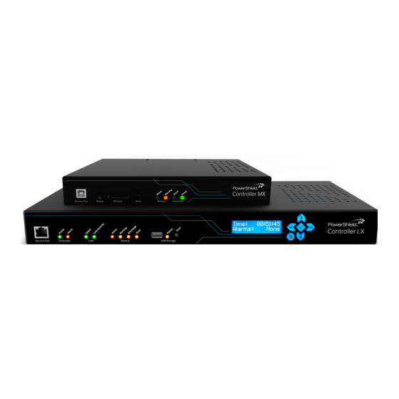
4.2 Controller The PowerShield Controller is supplied in a 1U high 19" rack case. The PowerShield Controller can be mounted in a 19" rack, on a wall, shelf, or similar using the mounting brackets provided. Ensure there is safe access to the rear connector panel and cable tray. -
Page 11: Hub Ports And Bbus Communication
25m (82ft). Contact PowerShield if longer distances are required. Each PowerShield Controller hub port is capable of supporting 1 Hub and up to 32 mSensors. For strings with a large number of blocks, additional mSensors will need to be used. These can be connected to spare Controller hub ports using an adaptor available from PowerShield that converts the Controller hub port CAT5 cable to 4-core BBus interconnect cable. -
Page 12: Hub
The PowerShield Controller communicates with the Hubs via the Controller hub ports, connected using CAT5 cable. It also supplies 24VDC power to the Hubs over this cable. Up to eight Hubs can be connected to a single PowerShield Controller, 1 per Controller hub port. This allows up to eight strings to be monitored with one PowerShield Controller. -
Page 13: Msensor
ID starting at ID 201. The PowerShield Controller communicates with the mSensors via the Controller hub ports using the BBus daisy chain communication bus. The mSensors should be connected to the PowerShield Hub using 4-core BBus interconnect cable via the 4-pin Modular Jack connectors on each device. -
Page 14: Installation
(not supplied), wall, shelf, or similar using the mounting brackets provided. Ensure there is safe access to the rear connector panel and cable tray. When the PowerShield Controller is powered up, it will emit an audible alert and the green Power LED will light. Other LEDs on the front panel may also light. -
Page 15: Block Terminal Tags
Do not bend the tags as this can damage the connector crimp and/or result in poor or loose connections with the mSensor power leads. Poor connections can have significant impact on impedance measurement. PowerShield reserves the right to void warranties where terminal tags are bent or modified. 5.4 Mounting Rail for Hubs and mSensors The mounting rail for the Hubs and mSensors can be fitted in any orientation and can be used with both battery racks and cabinets. -
Page 16: Msensor Power Leads
5.5 mSensor Power Leads Fit the mSensor power leads to the block terminal tags with the correct polarity. Ensure the dual power leads are connected across an ‘in series’ pair of batteries. Power leads are available with or without Block Temperature sensors. Refer to Appendix 6 for the recommended method of connecting the mSensor power leads. -
Page 17: Connect Msensors To Blocks
(where applicable). Insert the Hubs into the same mounting rail as the mSensors and connect CAT5 cable from the PowerShield Controller hub ports to each Hub. The Hub LED should flash orange if all is correct. A full list of Hub LED states is available in Appendix 2. -
Page 18: Connect Bbus Cables
Connect the mSensors and Hub using suitable lengths of BBus interconnecting cables in a daisy chain fashion. Note that each PowerShield Controller hub port must not have more than 33 devices connected to it (1 Hub and up to 32 mSensors). -
Page 19: Install Current Transducer
5.9 Install Current Transducer A current transducer (CT) is required per string to measure string current. Install the current transducer anywhere on the primary string conductor and plug the current transducer cable into the Current connector of the PowerShield Hub. NOTE: Ensure the current transducer selected has the appropriate rating for the expected string charge and discharge currents. -
Page 20: Connect Ambient Temperature Probe(S)
Check that all installed parts are performing as expected and secure all cables with appropriate strain relief. Complete the forms as in Appendix 12, connect to the Service Port Ethernet connector on the front of the PowerShield Controller and configure the system. -
Page 21: Appendix 1 - Controller Panels
• certain events occur. Refer to Appendix 5 for details of the relay terminals. Auxiliary Inputs: The PowerShield Controller has 2 dry contact inputs that can be used to read the state of • external devices. Refer to Appendix 5 for details of the Auxiliary Inputs. - Page 22 3 (Right) DC supply negative The DC input models are supplied with a mating female screw terminal plug. Refer to Appendix 8 for wiring details of the DC input model plug. Cable Tray: The case features a cable tray that extends beyond the rear panel connectors. Cables can be •...
-
Page 23: Appendix 2 - Led Behaviour
Appendix 2 – LED Behaviour PowerShield Controller LEDs The PowerShield Controller has LEDs on the front panel for on-site information. They will exhibit varying behaviour as described below: Name Colour Description Controller Power Green On continuously when powered. Controller Alarm On continuously if the PowerShield Controller has an internal system fault. -
Page 24: Msensor And Hub Leds
Device is detected and operating as normal. No warnings or alarms detected. Orange Double Flash Device is receiving communication but has not been detected by the PowerShield Controller. White Continuous Applies to Hub only. Device is in boot loader mode and waiting for commands. -
Page 25: Appendix 3 - Controller Lcd
Appendix 3 – Controller LCD The PowerShield Controller LCD can be used to view system information. The information is displayed by pressing the keypad buttons to access the required levels as shown below. The buttons operate as follows: Use the buttons to scroll through the menu levels. -
Page 26: Appendix 4 - Communication Options
The RS-485 card implements 2-wire (half-duplex) transmission. The RS-485 signals can be accessed at the 4-way screw terminal connector on the rear panel of the PowerShield Controller as shown below. If more than one Slave is on the RS-485 bus, connect the additional Slaves using a daisy-chain approach and join the signal wires at the 4-way connector. -
Page 27: Appendix 5 - Relays And Auxiliary Inputs
Auxiliary Inputs The PowerShield Controller has two auxiliary inputs that can be used to read the state of a dry contact switch in third party equipment. To activate the auxiliary input simply short the terminals of the non-polarised two way connector. -
Page 28: Appendix 6 - Msensor Power Lead Connection
Appendix 6 – mSensor Power Lead Connection It is important to connect and install the mSensor power lead correctly. The following diagrams show the recommended method of connecting an mSensor to blocks with 2 or 4 terminals per block. Failure to connect and install the mSensor power lead correctly may lead to unacceptable variation in readings between sensors. -
Page 29: Single Msensor And Block With 2 Terminals
Single mSensor and Block with 2 Terminals Single mSensor Power Lead Wires Wire Function / Block Connection Positive Power wire for sensor. Connect to positive terminal of Block. Brown Positive Sense wire for Block. Blue Negative Sense wire for Block. Black Power return wire for sensor. -
Page 30: Dual Msensor And Blocks With 4 Terminals
Dual mSensor and Blocks with 4 Terminals Dual mSensor Power Lead Wires Wire Function / Block Connection Positive Power wire for sensor. Connect to positive terminal of Block A. Yellow Positive Sense wire for Block A. Green Negative Sense wire for Block A. Brown Positive Sense wire for Block B. -
Page 31: Single Msensor And Block With 4 Terminals
Single mSensor and Block with 4 Terminals Single mSensor Power Lead Wires Wire Function / Block Connection Positive Power wire for sensor. Connect to positive terminal of Block. Brown Positive Sense wire for Block. Blue Negative Sense wire for Block. Black Power return wire for sensor. -
Page 32: Msensor Power Leads With Block Temperature
mSensor Power Leads with Block Temperature Dual mSensor Single mSensor mSensor Power Leads without Block Temperature Dual mSensor Single mSensor ___________________________________________________________________________________________________________ Part Number 6300-095D Page 32 of 43... -
Page 33: Appendix 7 - 4-Wire / Kelvin Connection
Appendix 7 – 4-Wire / Kelvin Connection This article explains the 4-wire or Kelvin connection measurement technique in general terms. It is not intended as an in- depth guide to making high accuracy measurements of battery impedance. Resistance Resistance is commonly measured by passing a known test current through the resistance under test and measuring the corresponding voltage. -
Page 34: 4-Wire/Kelvin Resistance Measurement
4-Wire/Kelvin Resistance Measurement To reduce the effect of lead and contact resistances, the 4-wire or Kelvin connection method can be used. This method requires 4 wires and thus 4 terminals at the meter as shown below. With this configuration, the test current is driven through the resistance under test using one set of leads called the Source leads. -
Page 35: Appendix 8 - Dc Model Controller Wiring
1.5mm The plug is fitted with a latch to secure it to the input socket of the PowerShield Controller. To remove the plug, press down on the latch with a screwdriver or suitable tool and pull the plug out. - Page 36 To wire and assemble the plug, please complete the following steps: 1. Remove the outer cable sheath and strip the ends of each wire as per below (lengths are in mm): 2. Insert the wires into the plug and tighten the contact screws. The wiring should be as follows: Plug Terminal Wire / Function...
-
Page 37: Appendix 9 - Controller Specifications
USB (Flash drive only) Rear 1000Base-T Ethernet (PowerShield Link software, Modbus TCP, SNMP) RS485 (optional) Hub Ports Capacity 1 PowerShield Hub and up to 32 PowerShield mSensors Connection RJ45 / CAT5 cable Maximum Distance 50m / 165ft (between Controller and Hub) Memory... -
Page 38: Appendix 10 - Hub Specifications
Appendix 10 – Hub Specifications Block Inputs up to 64 (via dual PowerShield mSensors) Type PowerShield mSensor Current Inputs 1 (provides string DC & AC current) Type Hall Effect Range 0A to ±2000A (depends on Current Transducer model used) Maximum Distance... -
Page 39: Appendix 11 - Msensor Specifications
1 or 2 (depends if using a single or dual mSensor) Block Type 1.2V NiCad, 2V, 4V, 6V, 8V, 12V, 16V Lead Acid Nominal Voltage NiCad Voltage Range 0.8 – 1.9V 1.6 – 2.6V 4.8 – 7.8V 9.6 – 15.6V Voltage Resolution 1mV dc, 1mV ac... -
Page 40: Appendix 12 - Powershield 8 Installation Forms
Appendix 12 - PowerShield 8 Installation Forms 6300-107 Facility Information Form (FIF) Facility Information Company/Customer: Facility Name: Facility Address: Total Number Strings: Total Number PowerShield 8 Systems: Installed by: Date: Notes ___________________________________________________________________________________________________________ Part Number 6300-095D Page 40 of 43... -
Page 41: 6300-108 Powershield 8 Controller Information Form (Cif)
6300-108 PowerShield 8 Controller Information Form (CIF) PRINT OUT AS MANY COPIES OF THIS FORM AS REQUIRED Facility Name: ............Controller Details System Name: Strings: No. Monitored: Details (No. Blocks/Voltage): Port 1: Connected (Yes / No): Configuration (DHCP / Manual): Manual Config.:... -
Page 42: 6300-109 Powershield 8 String Information Form (Sif)
6300-109 PowerShield 8 String Information Form (SIF) PRINT OUT AS MANY COPIES OF THIS FORM AS REQUIRED Facility Name: ............PowerShield 8 System Name: ......... String # / Name: No. mSensors (Singles / Duals): Block Details Hub Details Block Block... -
Page 43: 6300-110 Powershield 8 Block Mapping Form (Bmf)
6300-110 PowerShield 8 Block Mapping Form (BMF) PRINT OUT AS MANY COPIES OF THIS FORM AS REQUIRED Facility Name: ............PowerShield 8 System Name: ......... String # / Name: Controller Port # / Hub ID: Reverse Block Numbering (Yes/No): Block #...
Need help?
Do you have a question about the 8 and is the answer not in the manual?
Questions and answers