Table of Contents
Advertisement
Quick Links
Download this manual
See also:
Installation Manual
Advertisement
Table of Contents

Related Manuals for Promise Technology PEGASUS R6


Summary of Contents for Promise Technology PEGASUS R6
- Page 1 EGASUS R6, R4 Product Manual Version 1.0...
- Page 2 You should back up all data before installing any drive controller or storage peripheral. PROMISE Technology is not responsible for any loss of data resulting from the use, disuse or misuse of this or any other PROMISE Technology product. Notice Although PROMISE Technology has attempted to ensure the accuracy of the content of this document;...
-
Page 3: Table Of Contents
Contents Chapter 1: Introduction to Pegasus ......1 About This Manual ........1 Architecture . - Page 4 Pegasus R6, R4 Product Manual Chapter 3: Management with the Promise Utility, cont. Managing Subsystems ........21 Viewing Subsystem Information .
- Page 5 Chapter 1: Introduction Chapter 3: Management with the Promise Utility, cont. Managing Physical Drives, cont. Making Physical Drive SMART Log Settings ....42 Clearing a Stale or a PFA Condition .....43 Forcing a Physical Drive Offline .
- Page 6 Pegasus R6, R4 Product Manual Chapter 4: Technology Background ......73 Disk Arrays ......... . .73 Media Patrol .
- Page 7 Chapter 1: Introduction Chapter 5: Troubleshooting, cont. Disk Array and Logical Drive Problems .....110 Disk Array Degraded/Logical Drive Critical ....110 Disk Array Offline/Logical Drive Offline .
- Page 8 Pegasus R6, R4 Product Manual viii...
-
Page 9: Chapter 1: Introduction To Pegasus
(SOHO) users, and AV professionals. About This Manual This Product Manual describes how to setup, use, and maintain the Pegasus R6 and R4 unit. It also describes how to use the Promise Utility software that you install and run on your Macintosh computer. -
Page 10: Architecture
Pegasus R6, R4 Product Manual Warning A Warning notifies you of probable equipment damage or loss of data, or the possibility of physical injury, and how to avoid them. Architecture The Pegasus architecture is based on a state-of-the-art PMC Sierra 8011... -
Page 11: Specifications
Chapter 1: Introduction to Pegasus Specifications • Physical drive support: • 2.5-inch and 3.5-inch SATA hard disk drives • Additional storage using multiple Pegasus enclosures • SATA specification of 3 Gb/s transfers with CRC error-checking • Hot-swapping of physical drives •... -
Page 12: Client Os Support
Pegasus R6, R4 Product Manual Client OS Support The following client operating systems support the Pegasus unit: • Mac OS 10.6 and higher • MacBook Pro/iMac Software Update 1.5 Utility OS Support The following client operating systems support the Promise Utility: •... -
Page 13: Chapter 2: Installation And Setup
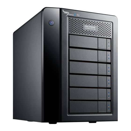
Chapter 2: Installation and Setup This chapter contains the following topics: • Unpacking the Pegasus Unit (page 5) • Connecting to your Mac Computer (page 7) • Connecting the Power (page 9) • Installing the Software (page 10) • Setting up the Pegasus Unit (page 13) Unpacking the Pegasus Unit The Pegasus box contains the following items: •... - Page 14 Pegasus R6, R4 Product Manual Figure 1. Pegasus R4 front view. The R6 is similar Power Button/LED Drive Carrier Thunderbolt Link LEDs Drive Power/ Status LED Drive Activity Figure 2. Pegasus R4 back view. The R6 is similar Thunderbolt Ports...
-
Page 15: Connecting To Your Mac Computer
Chapter 2: Installation and Setup Connecting to your Mac Computer Connect a Thunderbolt cable from one of the Thunderbolt ports on the back of the Pegasus to the Thunderbolt port on your Mac computer. Figure 3. Thunderbolt and power connections on a Mac computer Thunderbolt ports Pegasus system MacBook Pro... -
Page 16: Daisy-Chaining Multiple Pegasus Units
Pegasus R6, R4 Product Manual Daisy-Chaining Multiple Pegasus Units To daisy-chain multiple Pegasus units: Connect a Thunderbolt cable from one of the Thunderbolt ports on the back of your Mac computer to one of the Thunderbolt ports on the first Pegasus unit. -
Page 17: Connecting The Power
Chapter 2: Installation and Setup Connecting the Power To power the Pegasus unit: Attach the power cord on the back of the Pegasus unit. See page 7,Figure 3. Plug the other end into a power source. Press the Power Button. See Figure 5. -
Page 18: Installing The Software
Pegasus R6, R4 Product Manual Installing the Software The Pegasus unit ships ready to use without configuration or set-up. These instructions are for users who plan to: • Install their own physical drives • Configure the Pegasus manually Software installation involves two separate operations: •... -
Page 19: Driver Installation: Macintosh
Chapter 2: Installation and Setup Figure 6. Software Update dialog box Driver Installation: Macintosh To install the driver software onto your computer: Insert the CD into your computer’s DVD-ROM. Double-click the driver installer icon (right). The Welcome dialog box appears. Click the Continue button. -
Page 20: Software Installation: Macintosh
Pegasus R6, R4 Product Manual Software Installation: Macintosh To install the Promise Utility software onto your computer: Insert the CD into your computer’s DVD-ROM. Double-click the Promise Utility installer icon (right). The Welcome dialog box appears. Click the Continue button. -
Page 21: Setting Up The Pegasus Unit
Chapter 2: Installation and Setup Setting up the Pegasus Unit The Pegasus unit ships ready to use without configuration or set-up. These instructions are for users who plan to: • Install their own physical drives • Configure the Pegasus manually Pegasus set-up involves three steps: Opening the Promise Utility (below). -
Page 22: Unlocking The Ui
Pegasus R6, R4 Product Manual Unlocking the UI By default, the UI is locked to prevent unauthorized changes to your RAID system. When the UI is locked, you cannot create logical drives or change settings on the Pegasus unit. To unlock the UI: At the lower left screen of the Promise Utility window, click the closed lock icon. -
Page 23: Creating A Disk Array And Logical Drive
Chapter 2: Installation and Setup The first Pegasus unit is Pegasus R4 or (R6), the second is Pegasus R4-2 or (R6-2), the third is Pegasus R4-3 or (R6-3), and so on. Your computer lists the Pegasus units by the order in which they are recognized, not by the cable configuration. -
Page 24: Formatting Your Logical Drive
Pegasus R6, R4 Product Manual Figure 10.Wizard dialog box Choose the best method for your situation. See the table below. Suggested for Method User Options users who are Page Automatic None New to data storage Express General parameters Familiar with data storage... -
Page 25: Chapter 3: Management With The Promise Utility
Chapter 3: Management with the Promise Utility This chapter contains the following topics: • Accessing the Promise Utility (below) • Perusing the Promise Utility Interface (page 19) • Managing Subsystems (page 21) • Managing the RAID Controller (page 23) • Managing Subsystems (page 27) •... -
Page 26: Unlocking The Ui
Pegasus R6, R4 Product Manual Unlocking the UI By default, the UI is locked to prevent unauthorized changes to your RAID system. When the UI is locked, you are limited to viewing information and events. To open the lock: At the lower left screen of the Promise Utility window, click the closed lock icon. -
Page 27: Perusing The Promise Utility Interface
Chapter 3: Management with the Promise Utility Perusing the Promise Utility Interface The Promise Utility interface consists of menus and icons, each leading you to a specific function. Figure 1. The Promise Utility interface with the Dashboard displayed Dropdown menus Toolbar icons Dropdown Menus •... -
Page 28: Toolbar Icons
Pegasus R6, R4 Product Manual Toolbar Icons The default toolbar icons are listed here: • Dashboard icon – Displays the Dashboard and overview • Physical Drive icon – Displays the physical drive list, settings and functions • Logical Drive icon – Displays the logical drive list, settings and functions •... -
Page 29: Chapter 3: Management With The Promise Utility, Cont
Chapter 3: Management with the Promise Utility Managing Subsystems Subsystem management includes: • Viewing Subsystem Information (below) • Making Subsystem Settings (page 21) • Clearing Statistics (page 21) • Restoring Factory Default Settings (page 22) Viewing Subsystem Information The term subsystem refers to the Pegasus unit. To view subsystem information, do one of the following actions: •... -
Page 30: Restoring Factory Default Settings
Pegasus R6, R4 Product Manual • Click the Subsystem Information icon. • From the Admin menu, choose Subsystem Information. Click the Clear Statistics button. Type the word “confirm” in the field provided. Click the Confirm button. Restoring Factory Default Settings This feature restores settings to their default values. -
Page 31: Managing The Raid Controller
Chapter 3: Management with the Promise Utility Managing the RAID Controller RAID controller management includes: • Viewing Controller Information (below) • Viewing Controller Statistics (page 24) • Making Controller Settings (page 25) • Updating Firmware on the Pegasus Unit (page 25) •... -
Page 32: Viewing Controller Statistics
Pegasus R6, R4 Product Manual Advanced controller information includes: • Memory Type • Memory Size • Flash Type • Flash Size • NVRAM Type • NVRAM Size • Preferred Cache Line Size • Cache Line Size • Coercion * •... -
Page 33: Making Controller Settings
Chapter 3: Management with the Promise Utility Note To clear controller statistics, see “Clearing Statistics” on page 21. Making Controller Settings To make controller settings: Do one of the following actions, • Click the Dashboard icon, then click the Controller link. •... -
Page 34: Making Buzzer Settings
Pegasus R6, R4 Product Manual Making Buzzer Settings To make buzzer settings: Do one of the following actions, • Click the Dashboard icon, then click the Controller link. • From the Device menu, choose Component List. Mouse-over and click the buzzer, then click the Settings button. -
Page 35: Managing Subsystems
Chapter 3: Management with the Promise Utility Managing Subsystems Enclosure management includes the following functions: • Viewing the Subsystem Information (page 27) • Viewing Temperature Sensor Information (page 27) • Locating a Subsystem (page 28) Viewing the Subsystem Information To access subsystem information: Do one of the following actions, •... -
Page 36: Locating A Subsystem
Pegasus R6, R4 Product Manual Mouse-over and click the Enclosure, then click the View button. Scroll down until you see Temperature Sensors. Enclosure information includes: • ID – 1 • Status – = Normal. = Warning. = Critical. • Location – Not applicable for Pegasus •... -
Page 37: Managing Background Activities
Chapter 3: Management with the Promise Utility Managing Background Activities Background activity management includes: • Viewing Current Background Activities (page 29) • Viewing Scheduled Background Activities (page 30) • Adding a Scheduled Background Activity (page 30) • Changing a Background Activity Schedule (page 31) •... -
Page 38: Viewing Scheduled Background Activities
Pegasus R6, R4 Product Manual Viewing Scheduled Background Activities To view a list of scheduled background activities: From the Admin menu, choose Background Activities. Click the Scheduler button. The list of scheduled background appears. Adding a Scheduled Background Activity To add a new scheduled background activity: From the Admin menu, choose Background Activities. -
Page 39: Changing A Background Activity Schedule
Chapter 3: Management with the Promise Utility • Select LD – Check the boxes for the logical drives to run Redundancy Check. Check at least one logical drive. Click the Save button. To return to currently running background activities, click the Background Activities button. -
Page 40: Enabling Or Disabling A Scheduled Background Activity
Pegasus R6, R4 Product Manual • Select LD – Check the boxes for the logical drives to run Redundancy Check. Check at least one logical drive. Click the Save button. To return to currently running background activities, click the Background Activities button. -
Page 41: Redundancy Check
Chapter 3: Management with the Promise Utility See “Making Disk Array Settings” on page 53, “Running Media Patrol on your Physical Drives” on page 44, and “Media Patrol” on page 73. Making Media Patrol Settings To make Media Patrol settings: From the Admin menu, choose Background Activities. -
Page 42: Rebuild
Pegasus R6, R4 Product Manual earlier configurations. For this reason, Initialization is recommended whenever you create a logical drive. See “Initializing a Logical Drive” on page 63 and “Initialization” on page 89. Making Initialization Settings To make initialization settings: From the Admin menu, choose Background Activities. -
Page 43: Migration
Chapter 3: Management with the Promise Utility Click the Rebuild Rate dropdown menu and choose a rate: • Low – Fewer system resources to the Rebuild, more to data read/write operations. • Medium – Balances system resources between the Rebuild and data read/write operations. -
Page 44: Transition
Pegasus R6, R4 Product Manual PDM can be triggered automatically by Media Patrol. Also see “Running PDM on a Logical Drive” on page 66 and “PDM” on page 73. Making PDM Settings To make PDM settings: From the Admin menu, choose Background Activities. -
Page 45: Synchronization
Chapter 3: Management with the Promise Utility Click the Confirm button. Click the X icon to close the background activities panel. Synchronization Synchronization is automatically applied to logical drives when they are created. Synchronization recalculates the redundancy data to ensure that the working data on the physical drives is properly in sync. -
Page 46: Managing Physical Drives
Pegasus R6, R4 Product Manual Managing Physical Drives Physical drive management includes: • Viewing a List of Physical Drives (below) • Viewing Physical Drive Information (page 38) • Viewing Physical Drive SMART Log Information (page 40) • Locating a Physical Drive (page 41) •... - Page 47 Chapter 3: Management with the Promise Utility • Physical Drive ID – ID number of the physical drive • Location – Enclosure number and slot number • Alias – If assigned • Physical Capacity – Total capacity in GB • Configurable Capacity –...
-
Page 48: Viewing Physical Drive Statistics
Pegasus R6, R4 Product Manual Viewing Physical Drive Statistics To view physical drive statistics: Do one of the following actions: • Click the Physical Drive icon. • From the Device menu, choose Physical Drive. Mouse-over and click the physical drive you want then click the View button. -
Page 49: Locating A Physical Drive
Chapter 3: Management with the Promise Utility • SMART Health Status – OK is normal • SCT Status Version • SCT Version • SCT Support Level • Current Temperature • Power Cycle Max Temperature • Power Cycle Min Temperature • Lifetime Max Temperature •... -
Page 50: Making Individual Physical Drive Settings
Pegasus R6, R4 Product Manual Click the Global Physical Drive Settings button. Check the boxes to enable, uncheck to disable. • Enable Write Cache • Enable Read Look Ahead Cache • Enable Command Queuing Click the Save button. Click the X icon to close the settings panel. -
Page 51: Clearing A Stale Or A Pfa Condition
Chapter 3: Management with the Promise Utility Clearing a Stale or a PFA Condition Stale – The physical drive contains obsolete disk array information. PFA – The physical drive has errors resulting in a prediction of failure. Be sure you have corrected the condition by a physical drive replacement, rebuild operation, etc., first. -
Page 52: Running Media Patrol On Your Physical Drives
Pegasus R6, R4 Product Manual Running Media Patrol on your Physical Drives Media Patrol is a routine maintenance procedure that checks the magnetic media on each disk drive. Media Patrol checks are enabled by default on all disk arrays and spare drives. Media Patrol is concerned with the media itself, not the data recorded on the media. -
Page 53: Managing Disk Arrays
Chapter 3: Management with the Promise Utility Managing Disk Arrays Disk array management includes: • Viewing a List of Disk Arrays (below) • Viewing Disk Array Information (page 45) • Creating a Disk Array Manually (page 46) • Creating a Disk Array and Logical Drive with the Wizard (page 47) •... -
Page 54: Creating A Disk Array Manually
Pegasus R6, R4 Product Manual • Disk Array ID – DA0, DA1, etc. • Alias – If assigned • Operational Status – OK, Degraded, or Offline • Media Patrol – Enabled or disabled on this array • PDM – Enabled or disabled on this array •... -
Page 55: Creating A Disk Array And Logical Drive With The Wizard
Chapter 3: Management with the Promise Utility The drive carriers turn blue when you click them. The physical drives’ ID numbers appear in the field below the diagram. When you have finished your settings and choices, click the Submit button. The new array appears in the list. - Page 56 If you agree with the proposed configuration, click the Submit button. The Wizard creates your disk array and logical drive. If you have a Pegasus R6, the Wizard also creates a spare drive. • If you do NOT agree with the proposed configuration, click the Dashboard icon, click the Click here to create one link, and then click either the Express or Advanced button.
- Page 57 • Performance – The highest possible read/write speed • Spare Drive – A hot spare drive (Pegasus R6 only) • Mixing SATA/SAS Drive – Not applicable In the Number of Logical Drives field, type the number of logical drives you want to make from this disk array.
- Page 58 If you accept these parameters, click the Submit button. The Wizard creates your disk array and logical drives. If you have a Pegasus R6, the Wizard also creates a spare drive. • If you do NOT accept these parameters, click the Back button, then...
- Page 59 Chapter 3: Management with the Promise Utility Choosing Advanced Configuration This option enables you to directly specify all parameters for a new disk array, logical drives, and spare drives. To use the Advanced Configuration Wizard: From the Storage menu choose Wizard. Click the Advanced button.
- Page 60 Pegasus R6, R4 Product Manual • Choose a Write (cache) Policy. The choices are WriteThru (write through) and WriteBack. Write back requires a Read Cache or Read Ahead Read Cache Policy. • RAID 6 only. Choose a scheme from the dropdown menu.
-
Page 61: Making Disk Array Settings
Chapter 3: Management with the Promise Utility Click the Finish button to close the Wizard. Formatting your Logical Drives If you left the Format box checked under Task 2 – Logical Drive Creation, your logical drives are formatted automatically. If you UNchecked the Format box, you must format your logical drives manually. See “Formatting Logical Drives”... -
Page 62: Deleting A Disk Array
Pegasus R6, R4 Product Manual • From the Storage menu, choose Disk Array. Mouse-over and click the disk array you want then click the Locate button. The Drive Power/Status LED for the physical drives that make up the disk array blink blue and orange for one minute. -
Page 63: Rebuilding A Disk Array
Chapter 3: Management with the Promise Utility Remove the physical drives and install them in their new location. See the “Replacing a Physical Drive” on page 107 for more information. Rebuilding a Disk Array When you rebuild a disk array, you are actually rebuilding the data on one of its physical drives. - Page 64 Pegasus R6, R4 Product Manual Pausing and Resuming a Rebuild To pause or resume a Rebuild: From the Admin menu, choose Background Activities. Mouse-over Rebuild and click the Pause or Resume button. Stopping a Rebuild To stop means to cancel a Rebuild: From the Admin menu, choose Background Activities.
-
Page 65: Managing Logical Drives
Chapter 3: Management with the Promise Utility Managing Logical Drives Logical drive management includes: • Viewing a List of Logical Drives (below) • Viewing Logical Drive Information (page 58) • Viewing Logical Drive Statistics (page 59) • Making Logical Drive Settings (page 59) •... -
Page 66: Viewing Logical Drive Information
Pegasus R6, R4 Product Manual Viewing Logical Drive Information To view logical drive information: Do one of the following actions: • Click the Logical Drive icon. • From the Storage menu, choose Logical Drive. The list of logical drives appears. -
Page 67: Viewing Logical Drive Statistics
Chapter 3: Management with the Promise Utility Click the X icon to close the information panel. Viewing Logical Drive Statistics To view logical drive statistics: Do one of the following actions: • Click the Logical Drive icon. • From the Storage menu, choose Logical Drive. The list of logical drives appears. -
Page 68: Viewing Logical Drive Check Tables
Pegasus R6, R4 Product Manual Make setting changes as required: • Enter, change, or delete the alias in the Alias field. Maximum of 32 characters; letters, numbers, space between characters, and underline. • Choose a Read (cache) Policy. Read Cache, Read Ahead, and No Cache are available. -
Page 69: Creating A Logical Drive Manually
Chapter 3: Management with the Promise Utility Click the X icon to close the information panel. To clear the check tables, see “Clearing Statistics” on page 21. Creating a Logical Drive Manually This feature creates a logical drive only. You can also use the Wizard to create a disk array with logical drives and spare drives at the same time. -
Page 70: Formatting Your Logical Drives
Pegasus R6, R4 Product Manual • If you want the Promise Utility to format your logical drives, leave the Format box checked. For additional format options, see “Formatting Logical Drives” on page 90. Click the Add button. The new logical drive appears on the list at the right. -
Page 71: Deleting A Logical Drive
Chapter 3: Management with the Promise Utility Figure 11. Running the Locate function to identify a disk array Drive Power/Status LEDs blink blue and orange Deleting a Logical Drive Caution When you delete a logical drive, all the data on the logical drive is lost. -
Page 72: Redundancy Check On A Logical Drive
Pegasus R6, R4 Product Manual • Quick Initialization – Check the box and enter a value in the Quick Initialization Size field. This value is the size of the initialization blocks in • Full Initialization – Do not check the box. Enter a hexadecimal value in the Initialization Pattern in Hex field or use the default 00000000 value. -
Page 73: Migrating A Logical Drive
Chapter 3: Management with the Promise Utility Pausing and Resuming a Redundancy Check To pause or resume a Redundancy Check: From the Admin menu, choose Background Activities. The list of background activities appears. Mouse-over Redundancy Check and click the Pause or Resume button. Stopping a Redundancy Check To stop is to cancel the Redundancy Check: From the Admin menu, choose Background Activities. -
Page 74: Running Pdm On A Logical Drive
Pegasus R6, R4 Product Manual From the dropdown menu, choose a target RAID level. The choice of RAID levels depends the number of physical drives in the disk array. See the Note below. In the Capacity field, accept the current capacity. - Page 75 Chapter 3: Management with the Promise Utility Pausing and Resuming PDM To pause or resume PDM: From the Admin menu, choose Background Activities. The list of background activities appears. Mouse-over PDM and click the Pause or Resume button. Stopping PDM To stop is to cancel PDM: From the Admin menu, choose Background Activities.
-
Page 76: Managing Spare Drives
Pegasus R6, R4 Product Manual Managing Spare Drives Spare drive management includes: • Viewing a List of Spare Drives (below) • Viewing Spare Drive Information (page 68) • Creating a Spare Drive Manually (page 69) • Making Spare Drive Settings (page 70) •... -
Page 77: Creating A Spare Drive Manually
Chapter 3: Management with the Promise Utility • Physical Drive ID – ID number of the physical drive chosen for this spare • Location – Enclosure number and slot number • Model Number – Make and model of the physical drive •... -
Page 78: Making Spare Drive Settings
Pegasus R6, R4 Product Manual In the Create Spare Drive diagram, click a drive to choose it for your spare. The drive carrier turns blue when you click it. The physical drive’s ID number appears in the field below the diagram. -
Page 79: Deleting A Spare Drive
Chapter 3: Management with the Promise Utility After the “Spare Check completed” message appears, click the View button to see Spare Check Status. Deleting a Spare Drive This action requires Administrator or a Super User privileges. To delete a spare drive: Do one of the following actions: •... - Page 80 Pegasus R6, R4 Product Manual Pausing and Resuming a Transition To pause or resume Transition: From the Admin menu, choose Background Activities. The list of background activities appears. Mouse-over Transition and click the Pause or Resume button. Stopping, Pausing or Resuming a Transition To stop is to cancel a Transition: From the Admin menu, choose Background Activities.
-
Page 81: Chapter 4: Technology Background
Chapter 4: Technology Background This chapter covers the following topics: • Disk Arrays (below) • Logical Drives (page 75) • Formatting Logical Drives (page 90) • Spare Drives (page 92) • RAID Controllers (page 98) Disk Arrays Disk array technology includes: •... - Page 82 Pegasus R6, R4 Product Manual your data to a spare disk drive BEFORE the disk drive fails and your logical drive goes Critical. The following actions trigger PDM: • A disk drive with unhealthy status (see below) • Media Patrol finds a disk critical error •...
-
Page 83: Logical Drives
Chapter 4: Technology Background Logical Drives Logical drive technology includes: • RAID Levels (page 75) • RAID Level Migration (page 84) • Stripe Size (page 88) • Sector Size (page 88) • Initialization (page 89) RAID Levels RAID (Redundant Array of Independent Disks) allows multiple physical drives to be combined together in a disk array. - Page 84 Pegasus R6, R4 Product Manual Advantages Disadvantages • Implements a striped disk array, • Not a true RAID because it is not the data is broken down into fault-tolerant blocks and each block is written • The failure of just one drive...
- Page 85 Chapter 4: Technology Background RAID 1 – Mirror When a logical drive is mirrored, identical data is written to a pair of physical drives, while reads are performed in parallel. The reads are performed using elevator seek and load balancing techniques where the workload is distributed in the most efficient manner.
- Page 86 Pegasus R6, R4 Product Manual Advantages Disadvantages • Simplest RAID storage • Very high disk overhead – uses subsystem design only 50% of total capacity • Can increase read performance by processing data requests in parallel since the same data...
- Page 87 Chapter 4: Technology Background RAID 1E – Enhanced Mirror RAID 1E offers the security of mirrored data provided by RAID 1 plus the added capacity of more than two physical drives. It also offers overall increased read/ write performance plus the flexibility of using an odd number of physical drives. With RAID 1E, each data stripe is mirrored onto two physical drives.
- Page 88 RAID 5 is generally considered to be the most versatile RAID level. A RAID 5 on Pegasus R4 consists of three or four physical drives. A RAID 5 on Pegasus R6 consists of three to six physical drives. Advantages Disadvantages •...
- Page 89 RAID 6 is generally considered to be the safest RAID level. A RAID 6 on Pegasus R4 consists of four physical drives. A RAID 6 on Pegasus R6 consists of four to six physical drives. Advantages Disadvantages •...
- Page 90 Pegasus R6, R4 Product Manual RAID 10 – Mirror + Stripe Mirror + Stripe combines both of the RAID 1 and RAID 0 logical drive types. RAID 10 can increase performance by reading and writing data in parallel or striping, and duplicating the data, or mirroring.
- Page 91 Chapter 4: Technology Background Advantages Disadvantages • Implemented as a mirrored disk • Very high disk overhead – uses array whose segments are RAID only 50% of total capacity 0 disk arrays • High I/O rates are achieved thanks to multiple stripe segments Recommended Applications for RAID 10: •...
-
Page 92: Raid Level Migration
Pegasus R6, R4 Product Manual RAID Level Migration The term “Migration” means either or both of the following: • Change the RAID level of a logical drive. • Expand the storage capacity of a logical drive. On Pegasus, RAID level migration is performed on the disk array but it applies to the logical drives. - Page 93 Chapter 4: Technology Background RAID 0 A RAID 0 source logical drive can migrate to the following target logical drives: Target Requirements RAID 0 Add physical drives. RAID 1 2 physical drives only. Only a single-drive RAID 0 can migrate to RAID 1 by adding 1 physical drive.
- Page 94 Pegasus R6, R4 Product Manual RAID 1E A RAID 1E Source logical drive can migrate to the following Target logical drives: Target Requirements RAID 0 None. RAID 1E Add physical drives. RAID 5 3 physical drives minimum, 4 (R4) or 6 (R6).
- Page 95 Chapter 4: Technology Background RAID 6 A RAID 6 Source logical drive can migrate to the following Target logical drives: Target Requirements RAID 6 Add physical drives. Maximum of 4 (R4) or 6 (R6). See “Migrating a Logical Drive” on page 65. RAID 10 A RAID 10 Source logical drive can migrate to the following Target logical drives: Target...
-
Page 96: Stripe Size
Pegasus R6, R4 Product Manual Stripe Size Stripe Size, also called “Stripe Block Size,” refers to the size of the data blocks written to, and read from, the physical drives. Stripe Size is specified when you create a logical drive. You can choose Stripe Size directly when you use the Wizard Advanced Configuration function to create a logical drive. -
Page 97: Initialization
Chapter 4: Technology Background Initialization Initialization is done to logical drives after they are created from a disk array. Full initialization sets all data bits in the logical drive to a specified pattern, such as all zeros. The action is useful because there may be residual data on the logical drives left behind from earlier configurations. -
Page 98: Formatting Logical Drives
Pegasus R6, R4 Product Manual Formatting Logical Drives A RAID logical drive must also be formatted to be compatible with your computer. In this Product Manual, the term format includes both partition and format operations. You can format your logical drives using the: •... -
Page 99: Disk Utility
Chapter 4: Technology Background To format your logical drives using the Promise Utility with your own settings: In the Logical Drive list, mouse-over the logical drive you want to format, and click the Format button. Supply information as required: • Optional. -
Page 100: Spare Drives
Pegasus R6, R4 Product Manual Spare Drives Spare drive technology includes: • Definition (page 92) • Options (page 92) • Requirements (page 92) • Transition (page 93) Definition A spare drive is a physical drive that you designate to automatically replace the failed physical drive in a disk array. -
Page 101: Transition
Chapter 4: Technology Background • You to run the Transition function Transition Transition is the process of replacing a revertible spare drive that is currently part of a disk array with an unconfigured physical drive or a non-revertible spare. The revertible spare drive returns to its original status. - Page 102 Pegasus R6, R4 Product Manual Example Following is an example to explain the Transition function. Array Drives Spare Drive In the example above, there is a four-drive RAID 5 disk array and a global spare drive. Physical drives 1, 2, 3, and 4 belong to the disk array. Physical drive 5 remains unconfigured.
- Page 103 Chapter 4: Technology Background drive. In this example, physical drive 3 failed and the array is rebuilt using physical drive 6, the revertible spare drive. Array Drives When the rebuild is complete, the spare drive has replaced the failed drive. In this example, failed drive 3 was replaced by spare drive 6.
- Page 104 Pegasus R6, R4 Product Manual Automatic Transition At this juncture, you would replace the failed drive in slot 3 with a new one of the same or greater capacity. Array Drives Spare Drive When the Pegasus controller detects the new drive in slot 3, the controller: •...
- Page 105 Chapter 4: Technology Background Array Drives Spare Drive When the Manual Transition is finished, physical drives 1, 2, 4, and 5 belong to the disk array and physical drive 6 is a revertible spare drive. At this point, you would replace the drive in slot 3. The new drive in slot 3 remains unconfigured until you assign it to a disk array or as a spare.
-
Page 106: Raid Controllers
Pegasus R6, R4 Product Manual RAID Controllers RAID controller technology includes; • Cache Policy (page 98) • Capacity Coercion (page 98) Cache Policy As it is used with Pegasus, the term cache refers to any of several kinds of high- speed, volatile memory that hold data moving from your computer to the physical drives or vice-versa. - Page 107 Chapter 4: Technology Background The choices are: • GB Truncate – (Default) Reduces the useful capacity to the nearest 1,000,000,000 byte boundary. • 10GB Truncate – Reduces the useful capacity to the nearest 10,000,000,000 byte boundary. • Group Rounding – Uses an algorithm to determine how much to truncate. Results in the maximum amount of usable drive capacity.
- Page 108 Pegasus R6, R4 Product Manual...
-
Page 109: Chapter 5: Troubleshooting
Chapter 5: Troubleshooting • Responding to an Audible Alarm (below) • Checking LEDs (page 101) • Promise Utility (page 104) • Viewing the Event Logs (page 104) • Physical Drive Problems (page 106) • Disk Array and Logical Drive Problems (page 110) •... -
Page 110: Subsystem Leds
Pegasus R6, R4 Product Manual Subsystem LEDs The Pegasus subsystem LEDs are the Power Button and the Thunderbolt ports. State Power Button Thunderbolt LEDs Dark No power No connection Blue Normal Normal Flashing Blue — Activity Orange Booting or shutting down —... -
Page 111: Drive Carrier Leds
Chapter 5: Troubleshooting Drive Carrier LEDs The Pegasus unit spins up the disk drives sequentially to equalize power draw during start-up. After a few moments: • The Power/ Status LEDs turn blue. • The Activity LEDs turn blue if a drive is installed. The drive carrier Power/Status LEDs report the condition of the physical drives. -
Page 112: Promise Utility
Pegasus R6, R4 Product Manual Promise Utility If you can open the Promise utility, but you cannot create or delete disk arrays and logical drives, nor can you make settings changes, check the UI lock. See “Unlocking the UI” on page 18. -
Page 113: Event Severity Descriptions
Chapter 5: Troubleshooting • Event ID – Hexadecimal identifier of the event • Severity – (lowest to highest) Information, Warning, Minor, Major, Critical and Fatal • Time – Date and time the event happened. • Description – A description of the event in plain language. Event Severity Descriptions Level Meaning... -
Page 114: Physical Drive Problems
Pegasus R6, R4 Product Manual Physical Drive Problems Physical drive troubleshooting includes: • Diagnosis using the Promise Utility (below) • Locating a Physical Drive (page 107) • Replacing a Physical Drive (page 107) • Physical Drive Warning Message (page 109) Physical drives are the foundation of data storage. -
Page 115: Locating A Physical Drive
Chapter 5: Troubleshooting Locating a Physical Drive To locate a physical drive: Do one of the following actions: • Click the Physical Drive icon. • From the Device menu, choose Physical Drive. Mouse-over and click the physical drive you want then click the Locate button. - Page 116 Pegasus R6, R4 Product Manual To replace a physical drive: Press the release button to unlock the drive carrier. Release button The drive carrier handle swings out. Grasp the handle and gently pull the drive carrier out of the Pegasus unit and place it onto a static-free surface.
-
Page 117: Physical Drive Warning Message
Chapter 5: Troubleshooting Place the replacement drive into the carrier then install the four mounting screws. Tighten the screws just until they are snug. Position the drive carrier handle in outward position and slide the drive carrier back into the Pegasus unit. Press the drive carrier handle inward until it locks. -
Page 118: Disk Array And Logical Drive Problems
Pegasus R6, R4 Product Manual Disk Array and Logical Drive Problems Disk array and logical drive troubleshooting includes: • Disk Array Degraded/Logical Drive Critical (page 110) • Disk Array Offline/Logical Drive Offline (page 111) • Repairing an Offline Disk Array or Logical Drive (page 111) •... -
Page 119: Disk Array Offline/Logical Drive Offline
Chapter 5: Troubleshooting If there is no spare drive in the Pegasus unit, you must provide the replacement drive. See “Replacing a Physical Drive” on page 107. Disk Array Offline/Logical Drive Offline Disk arrays are made up of physical drives. Logical drives are created on the disk array. -
Page 120: Rebuilding A Disk Array
Pegasus R6, R4 Product Manual See “Locating a Physical Drive” on page 107. Replace the failed drive. See “Replacing a Physical Drive” on page 107. If the disk array had more than one physical drive, delete the disk array and re-create it. - Page 121 Chapter 5: Troubleshooting Migration Normally, if a physical drive or the controller fails during migration, the disk array goes critical, and you can rebuild it. Transport Transport is the action of moving the physical drives of a disk array: • To different slots in the same subsystem •...
-
Page 122: Unreadable Disk Warning
Pegasus R6, R4 Product Manual Unreadable Disk Warning Your Pegasus logical drive displays on the computer’s desktop as a removable-drive icon (right). If your computer’s operating system recognizes a logical drive but cannot access it, the computer might display a warning message. -
Page 123: Subsystem Problems
Chapter 5: Troubleshooting Subsystem Problems Subsystem problem troubleshooting includes: • Diagnosing a Subsystem Problem (below) • Overheating (page 116) • Power Supply (page 117) Diagnosing a Subsystem Problem Check System Status on the Dashboard tab. If a yellow ! or red X appears in the System Status box: Click the name link of the component with the red X icon. -
Page 124: Overheating
Pegasus R6, R4 Product Manual Overheating Overheating is a potentially serious condition because the excessively high temperatures can lead to physical drive failure and controller malfunction. Overheating usually results from: • Fan failure • Inadequate air circulation around the subsystem... -
Page 125: Power Supply
Chapter 5: Troubleshooting To cool down a Pegasus unit: • Correct any problems identified above. • Shut down the Pegasus unit. Press and hold the Power Button for a few seconds until the LED turns red. The Promise Utility displays the message: Unable to connect to the device. •... -
Page 126: Connection Problems
Pegasus R6, R4 Product Manual Connection Problems Connection problem troubleshooting includes: • Cables (below) • Daisy-Chains (page 119) Cables While the installation of the cables and components was correct, they don't function properly, or at all, because: • A connector is dirty or corroded •... -
Page 127: Daisy-Chains
Chapter 5: Troubleshooting Daisy-Chains If you have multiple Pegasus units daisy-chained together, all Pegasus units must be running to provide access to your volumes and the data they contain. If you shut down a Pegasus unit in the chain, that unit and those below it are effectively disconnected from your computer. - Page 128 Pegasus R6, R4 Product Manual...
-
Page 129: Chapter 6: Support
Chapter 6: Support • Contacting Technical Support (below) • Limited Warranty (page 127) • Returning Product For Repair (page 129) Contacting Technical Support Important You must register your Pegasus unit to receive support. Go to: https://support.promise.com/userRegistration.aspx Thank you! PROMISE Technical Support provides several support options for PROMISE users to access information and updates. - Page 130 Pegasus R6, R4 Product Manual Australia Apple Pre-Sales Toll Free: 1800-149-746 Apple Support Phone Toll Free: 1800-149-746 Apple Sales Email: apple@promise.com Technical Support (E-Support): https://support.promise.com Web site: http://www.promise.com/apple/ EMEA Netherlands Science Park Eindhoven 5228 5692 EG Son, The Netherlands Apple Pre-Sales Toll Free Phone (0830 to 1700): 0800-917-027...
- Page 131 Chapter 6: Support Germany Europaplatz 9 44269 Dortmund, Germany Apple Pre-Sales Toll Free Phone (0830 to 1700): 0800-187-3557 Apple Support Toll Free Phone (0830 to 1700): 0800-187-3557 Apple Support Toll Free Phone (After Hours, English only): 0800-187-3557 Apple Sales Email: apple@promise.com Technical Support (E-Support): https://support.promise.com...
- Page 132 Pegasus R6, R4 Product Manual Belguim Apple Pre-Sales Toll Free Phone (0830 to 1700): 0800-71915 Apple Support Toll Free Phone (0830 to 1700): 0800-71915 Apple Support Toll Free Phone (After Hours, English only): 0800-71915 Apple Sales Email: apple@promise.com Technical Support (E-Support): https://support.promise.com...
- Page 133 Chapter 6: Support China Room 1108, West Wing, Shi Chuang Plaza, 22 Information Road Shangdi IT Park, Haidian District, Beijing 100085 Apple Pre-Sales Toll Free: 86-10-8857-8085/8095 Apple Support Phone Toll Free: 86-10-8857-8085/8095 Fax: 86-10-8857-8015 Apple Sales Email: apple@promise.com Technical Support (E-Support): https://support.promise.com Web site: http://www.promise.com/apple/...
- Page 134 Pegasus R6, R4 Product Manual Japan 3F, Mura Matsu Bldg, 3-8-5, Hongo Bunkyo-ku Tokyo 113-0033, Japan Apple Pre-Sales Toll Free Phone (24x7 English only): 0066-3384-9021 Apple Support Toll Free Phone (24x7 English only): 0066-3384-9021 Apple Sales Email: apple@promise.com Technical Support (E-Support): https://support.promise.com...
-
Page 135: Limited Warranty
Chapter 6: Support Limited Warranty PROMISE Technology, Inc. (“PROMISE”) warrants that this product, from the time of the delivery of the product to the original end user: all components, except for the fan and power adapter, for a period of two (2) years;... - Page 136 Pegasus R6, R4 Product Manual to back up or otherwise save important data before installing any product and continue to back up your important data regularly. No other document, statement or representation may be relied on to vary the terms of this limited warranty.
-
Page 137: Returning Product For Repair
Return ONLY the specific product covered by the warranty (do not ship cables, manuals, diskettes, etc.), with a copy of your proof of purchase to: USA and Canada: PROMISE Technology, Inc. Customer Service Dept. Attn.: RMA # ______ 47654 Kato Road... - Page 138 Pegasus R6, R4 Product Manual You are responsible for the cost of insurance and shipment of the product to PROMISE. Note that damage incurred due to improper transport or packaging is not covered under the Limited Warranty. When repairing returned product(s), PROMISE may replace defective parts with new or reconditioned parts, or replace the entire unit with a new or reconditioned unit.
-
Page 139: Appendix A: Updates
Appendix A: Updates This appendix contains the following topics • Updating the Firmware (below) • Updating Drivers (page 133) • Updating the Software (page 134) Updating the Firmware Preparing the Pegasus Unit To update the firmware on the Pegasus unit: Download the latest firmware image file from PROMISE support: http://www.promise.com/support/ and save it to your computer. - Page 140 Pegasus R6, R4 Product Manual That information can help you decide whether to: • Wait until all activities are finished. • Pause or cancel the activities and proceed with the update. Updating the Firmware To update the firmware on the Pegasus unit: Click the Admin dropdown menu and choose Firmware Update.
-
Page 141: Updating Drivers
Appendix A: Updates Figure 1. Pegasus R4 front view. The R6 is similar Power Button/LED Updating Drivers To install an updated driver onto your computer: Download the latest driver installer file from PROMISE support: http://www.promise.com/support/ and save it to your computer. The driver installer file name has a .pkg (package) suffix. -
Page 142: Updating The Software
Pegasus R6, R4 Product Manual Updating the Software To install updated Promise Utility software onto your computer: Download the latest software installer file from PROMISE support: http://www.promise.com/support/ and save it to your computer. The software installer file name has a .pkg (package) suffix. -
Page 143: Appendix B: Important Information
Appendix B: Important Information GNU General Public License This product includes copyrighted third-party software licensed under the terms of the GNU General Public License. Please see the GNU General Public License (“GPL”) for the exact terms and conditions of this license at www.gnu.org. The GPL source code incorporated into the product is available for free download at our web site www.PROMISE.com/support/download/download_eng.asp. - Page 144 Pegasus R6, R4 Product Manual...
-
Page 145: Index
Index clear PFA condition about this manual stale condition ajar HDD from the backplane statistics alias 4, 10 client OS support controller controller disk array alias logical drive information physical drive statistics architecture create audible alarm disk array Auto Fix logical drive auto rebuild, enable spare drive... - Page 146 Pegasus R6, R4 Product Manual ESD warning event log drive activity NVRAM drive power/status runtime list event logs logical drives event severity spare drives expand logical drive locate disk array logical drive subsystem firmware update 14, 18 lock the UI...
- Page 147 Index Redundancy Check logical drive NVRAM event log settings replace a physical drive requirements for spare drives online capacity expansion defined restore default settings revertible spare drive OS, client supported runtime event log partition and format settings PDM settings background activities Pegasus buzzer architecture...
- Page 148 Pegasus R6, R4 Product Manual spare drive, cont. troubleshooting, cont. requirements NVRAM events revertible physical drives settings Promise utility Spare Check rebuild disk array or logical 71, 93 transition drive specifications repair disk array or logical drive statistics, controller subsystem...
Need help?
Do you have a question about the PEGASUS R6 and is the answer not in the manual?
Questions and answers