Table of Contents
Advertisement
VON DUPRIN
Installation Instructions
98/9975
®
Please give these instructions to building owner after device is installed
This product is covered by the
following patent numbers:
3,767,238
4,427,223
3,854,763
4,466,643
4,167,280
4,741,563
®
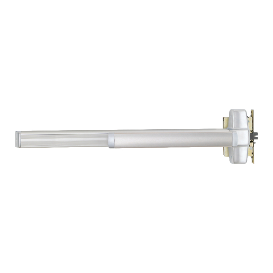
Series Mortise Exit Device
Devices covered by these instructions:
98/9975 Mortise Exit Device
98/9975-F (Fire) Mortise Exit Device
CD98/9975 (Cylinder Dogging) Mortise Exit Device
EL98/9975 (Electric Latch Retraction) Mortise Exit Device
98/9975-2 (Double Cylinder) Mortise Exit Device
• Screw chart ................................... 2
• Preparation chart ......................... 3
• Device installation ................... 4-5
• Optional equipment ................ 6-7
• Cut device ..................................... 8
Special tools needed:
#10-24 tap
#12-24 tap
Drill bits: #25, 1/8", 1/4",
5/16", 13/32"
Index:
FAX version 911374_00(2) Page 1 of 9
Advertisement
Table of Contents

Subscribe to Our Youtube Channel
Related Manuals for Von Duprin 98/9975 Series


Summary of Contents for Von Duprin 98/9975 Series
- Page 1 VON DUPRIN ® Installation Instructions 98/9975 ® Series Mortise Exit Device Devices covered by these instructions: 98/9975 Mortise Exit Device 98/9975-F (Fire) Mortise Exit Device CD98/9975 (Cylinder Dogging) Mortise Exit Device EL98/9975 (Electric Latch Retraction) Mortise Exit Device 98/9975-2 (Double Cylinder) Mortise Exit Device...
- Page 2 SCREW CHART Metal or wood door #12-12 x 12-24 x 1” Combination Surface mount or #10-24 X 1” Sex bolts (1-3/4” door) Sex bolts (2-1/4” door) #10-24 X 1-1/2” Surface mount (wood) #10 x 1-1/4” Wood screw - PACKAGED WITH TRIM - 990 Trims (1-3/4”...
- Page 3 PREPARATION CHART Go to instructions on next page before using Preparation Chart Center case - 4 holes Surface mount Sex bolts or 990 trims 1/4” Drill (device side) #25 Drill #10-24 tap 13/32” Drill (trim side) 1/2” dia. hole 1/4” 13/32”...
- Page 4 Align template along center Draw horizontal device line (C ) and mark door. center line (C ). Device template 2-3/4” Backset Mark 4 holes Mark 39-5/8” vertical C L to finished floor RHR Shown (LHR Opposite) Install mortise lock Prepare 4 center case into door.
- Page 5 Install outside locking cylinder Install trim (if using) and secure (if using) and finish installing device center case to door. mortise lock. See 7500 Mortise Lock Instructions #941019 1-1/2” Minimum clearance (with endcap removed) if device is too long for door, see “Cut Device”...
- Page 6 Adjust latch bolt. Install center case cover. Top view Pushbar Remove protective Adjustment film from pushbar screws Adjustment finger 3/4” Latch bolt Loosen adjustment screws and adjust finger in or out until latchbolt is fully Center case retracted (with pushbar down) and fully cover extended 3/4”...
- Page 7 OPTIONAL EQUIPMENT CD (CYLINDER DOGGING) 1. Remove mortise cylinder cam and reinstall in reverse (Figure 1). Std. mortise cylinder 2. Insert key and rotate cam to install the cylinder to the cover plate (Figure 2). 3. Remove key to slide cover plate in position in the mechanism case.
- Page 8 Solenoid draws 16 A inrush current from PS873. circuit Black Solenoid Solenoid must be wired to a PS873 logic board: board If 871-2 logic board, refer to Von Duprin instructions ELECTRICAL SPECIFICATIONS 941352. Voltage: 24 VDC If other 873 logic board, Current: 16 A inrush (0.3 sec.)
- Page 9 CUT DEVICE Measure amount to cut off device. Tape and mark area being cut. 1-1/2” minimum clearance Remove anti-rattle clip (with endcap removed) Tape Cover plate (flush to pushbar) Pushbar Note If 5/8” diameter wire access hole has been predrilled in door, cut device 5/16”...
Need help?
Do you have a question about the 98/9975 Series and is the answer not in the manual?
Questions and answers