Advertisement
Quick Links
*911403-00*
911403-00
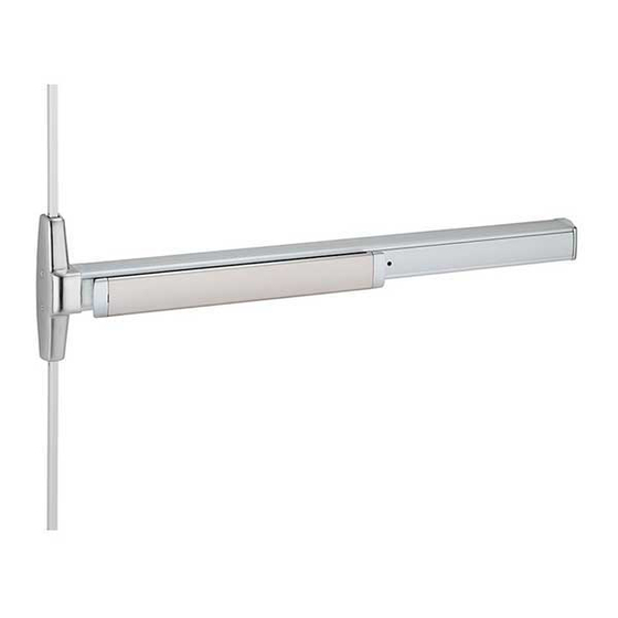
Surface Vertical Rod Exit Device
Please give these instructions to building owner after device is installed
33/3527A
Devices covered by these instructions:
33/3527A Surface Vertical Rod Exit Device
33/3527A-F (Fire) Surface Vertical Rod Exit Device
CD33/3527A Surface Vertical Rod Exit Device
EL33/3527A Surface Vertical Rod Exit Device
SS33/3527A Surface Vertical Rod Exit Device
Special tools needed:
#10-24 tap
Drill bits: #25, 1/8", 1/4",
5/16", 13/32"
Index:
• Screw chart ............................ 2
• Device installation ................ 3-6
• Cut top rod .............................. 7
• Install rod extension................. 7
• Optional equipment ................. 8
• Templates .......................... 9-14
Installation Instructions
Advertisement

Related Manuals for Von Duprin 33/3527A


Summary of Contents for Von Duprin 33/3527A
-
Page 1: Table Of Contents
Surface Vertical Rod Exit Device Installation Instructions Devices covered by these instructions: 33/3527A Surface Vertical Rod Exit Device 33/3527A-F (Fire) Surface Vertical Rod Exit Device CD33/3527A Surface Vertical Rod Exit Device EL33/3527A Surface Vertical Rod Exit Device SS33/3527A Surface Vertical Rod Exit Device... -
Page 2: Screw Chart
SCREW CHART Trim mount or sex bolts: 1/4-20 x 1” (1-3/4” door) (2-1/4” door) 1/4-20 x 1-1/2” #10-24 X 3/4” Surface mount or Sex bolts (1-3/4” door) #10-24 X 1-1/8” Sex bolts (2-1/4” door) #10-16 X 3/8” Thread cutting End cap 1/4-20 X 3/4”... -
Page 3: Device Installation
Figure backset and draw device center lines ( ) on door as shown. Backset is measured from outer edge of door as shown. Minimum stile is less glass stop (rectangular glass stop is recommended for stiles less than 2-1/8”) Stile width Backset Backset... - Page 4 Measure to determine Cut device to length. length to cut device. Prepare device for cutting 1-3/16” minimum clearance Tape (with end cap removed) Anti-rattle clip (remove while cutting) Cover plate (flush to pushbar) Pushbar Cut device square Note: Device must be cut square for proper end cap fit Cut device...
- Page 5 Install top latch and rod. Install top strike. 266 strike 260U strike For panic device For panic device 325 sex bolts application only application only (required) latch Top rod (longer of the two) 299/299F strike Shim to 3/16” If top rod is too long, see “Cut as shown 3/16”...
- Page 6 Adjust bottom rod with door Install bottom rod. open (top latch retracted). With door With door open: closed: Bottom #325 sex bolts (required) Latch bolt Latch bolt Bottom should clear floor should be latch and not bind on deadlocked strike (will not push in) Open and close door a few times and check for deadlocking when door is closed...
-
Page 7: Cut Top Rod
CUT TOP ROD 2. Cut rod. 1. Measure amount to cut off rod as shown below. Note: Rod cutting is required for doors shorter than 7’. Amount Drive out to cut off roll pin 3. Drill new hole. 1/8” dia. drill thru Use cut off *84”... -
Page 8: Optional Equipment
OPTIONAL EQUIPMENT CD (CYLINDER DOGGING) 1. Remove mortise cylinder cam and reinstall in reverse (Figure 1). Std. mortise cylinder 2. Insert key and rotate cam to install the cylinder to the cover plate (Figure 2). 3. Remove key to slide cover plate in position in the mechanism case. - Page 9 TOP TEMPLATE...
- Page 10 TOP TEMPLATE - CONTINUED Note: For 299/299F top strike use minimum backsets shown below. Double doors: 1-3/8” min. backset, 2-3/16” min. stile Single door: 1-7/8” min. backset, 2-11/16” min. stile...
- Page 11 BOTTOM TEMPLATE...
- Page 12 BOTTOM TEMPLATE - CONTINUED...
-
Page 13: Templates
33/3527A Device Template C L of device 3-1/8” Cut-out device side only 5/8” deep for wood door 7/8” of device 7/8” 1/4” Radius 3-1/8” 7/8” 19/32” Holes - 2 places 5/16” Drill inside 13/32” drill outside (sex bolts) 1/2” drill outside (trim) 1/4”... - Page 14 33/3527A Device Template Device 3-1/8” Cut-out device side only 5/8” deep for wood door 7/8” of device 7/8” 1/4” Radius 3-1/8” 7/8” 19/32” Holes - 2 places 5/16” Drill inside 13/32” drill outside (sex bolts) 1/2” drill outside (trim) 13/32” Drill thru (sex bolts) 1/2”...
- Page 16 © Allegion 2016 Customer Service Printed in U.S.A. 911403-00 Rev. 12/16-d 1-877-671-7011 www.allegion.com/us...
Need help?
Do you have a question about the 33/3527A and is the answer not in the manual?
Questions and answers