Advertisement
Quick Links
*911402-00*
33/35A Series
911402-00
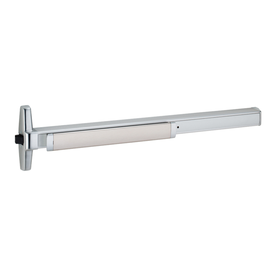
Rim Exit Device
Installation Instructions
Devices covered by these instructions:
33/35A Rim Exit Device
33/35A-F Rim Exit Device
CD33/35A Rim Exit Device
EL33/35A Rim Exit Device
SS33/35A Rim Exit Device
Dogging Key
(use with non-fire devices to lock down pushbar)
#10-24
Customer Service
© Allegion 2016
Printed in U.S.A.
911402-00 Rev. 05/16-d
1-877-671-7011
www.allegion.com/us
Advertisement

Related Manuals for Von Duprin 33/35A


Summary of Contents for Von Duprin 33/35A
- Page 1 *911402-00* 33/35A Series 911402-00 Rim Exit Device Installation Instructions Devices covered by these instructions: 33/35A Rim Exit Device 33/35A-F Rim Exit Device CD33/35A Rim Exit Device EL33/35A Rim Exit Device SS33/35A Rim Exit Device Dogging Key (use with non-fire devices to lock down pushbar)
-
Page 2: Screw Chart
SCrew Chart Screw application Device Subassembly Trim mount or sex bolts: Z\v-20 x1” (25 mm) 1C\v” (44 mm) door Z\v-20 x 1-Z\x” (38 mm) 2Z\v” (57 mm) door Metal door surface mount #10-24 x 1” (25 mm) (Yellow) #10 x 1Z\v” (32 mm) Wood screw Wood door surface mount Surface mount or Sex bolts #10-24 x C\v”... - Page 3 Draw horizontal device and strike center lines ( C L ). Install strike using two screws only at this time. Panic Device Install strike 1/16” past door side of stop * 39ZC\zn” (101.1 cm) from finished floor For double doors with a 1439 Strike (standard) mullion and strike already installed, use existing...
- Page 4 If using a 1439 strike, install wear strip. If not, go to Prepare lock side of door for device and trim. step 5. See trim instructions for Door pull side door preparation. side Wear strip See template for drill and cut-out information A.
- Page 5 If necessary, cut device. Install hinge stile mounting bracket. Prepare device for cutting Mark and prepare 2 mounting holes Mounting Tape bracket flush Anti-rattle clip (remove while cutting, then 1/4” drill inside replace after cutting) 13/32” drill outside Cover plate (flush to pushbar) 13/32”...
-
Page 6: 499F Strike Installation
Install 2 support screws and center case cover Install 2 support screws and center case cover End cap Remove protective film from pushbar Center 2 support case cover screws 499F StrIke InStaLLatIOn 1. Prepare and install screws through 2. Install strike hook and additional 3. - Page 7 OPtIOnaL equIPMent CD (Cylinder Dogging) Option Undog...
-
Page 8: Frame Preparation
1439 Strike 1439 Strike Frame Preparation RHR shown #25 Drill (LHR opposite) #10-24 tap 1/8” Drill pilot 1” deep 7/16” 1-9/16” to 7/16” Blade stop face of door... - Page 9 299/299F/1606 Strike Template 299F 1606 Strike Door Door Door Mullion Stop Stop Cut paper along this line and place on door stop against edge of door (see picture below) #25 Drill #10-24 tap 1/8” Drill pilot 1” deep Template 1-1/16” 1-1/16”...
- Page 10 This page intentionally left blank...
- Page 11 33/35A Rim device Line X-X is a reference line for trim and exit device alignment. C L of device Line X-X shown here should Template correspond to line X-X in the trim installation instructions 1/4” Holes - 2 places #25 drill inside #10-24 tap 1/8”...
- Page 12 33/35A Rim device Line X-X is a reference line for trim and exit device alignment. Line X-X shown Device Template here should correspond to line X-X in the trim installation instructions 1/4” Holes - 2 places #25 drill inside #10-24 tap...
Need help?
Do you have a question about the 33/35A and is the answer not in the manual?
Questions and answers