Von Duprin 33A Series Installation Instructions Manual
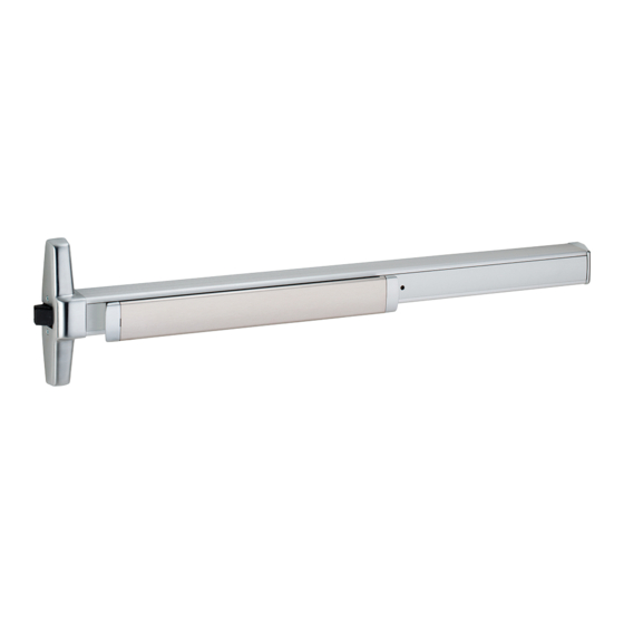
Rim exit device
Hide thumbs
Also See for 33A Series:
- Service manual (14 pages) ,
- Installation instructions manual (12 pages)
Advertisement
Quick Links
911402-00
Rim Exit Device
Special tools needed:
5/64" hex wrench
#10-24 tap
Drill bits: #25, 1/8", 1/4",
33/35A Series
Devices covered by these instructions:
33/35A Rim Exit Device
CD33/35A Rim Exit Device
EL33/35A Rim Exit Device
SS33/35A Rim Exit Device
5/16", 13/32"
Index:
Screw chart ............................ 2
Device installation ................ 3-5
Optional equipment ................. 6
Strike preparation ................ 7-8
Templates ........................... 9-10
Installation Instructions
Advertisement

Related Manuals for Von Duprin 33A Series


Summary of Contents for Von Duprin 33A Series
- Page 1 33/35A Series 911402-00 Rim Exit Device Installation Instructions Devices covered by these instructions: 33/35A Rim Exit Device CD33/35A Rim Exit Device EL33/35A Rim Exit Device SS33/35A Rim Exit Device Index: Special tools needed: Screw chart ......2 Device installation ....3-5 5/64”...
- Page 2 SCREW CHART Trim mount or sex bolts: 1/4-20 x 1” (1-3/4” door) (2-1/4” door) 1/4-20 x 1-1/2” Metal door surface mount #10-24 X 1” (Yellow) Wood door surface mount #10 X 1-1/4” Surface mount or #10-24 X 3/4” Sex bolts 1-3/4” door (silver) Sex bolts 2-1/4”...
- Page 3 Draw device center line ( Prepare frame for strike on door and frame as shown. using paper templates. See pages 7 and 8 for strike templates and frame preparation dimensions. RHR shown (LHR opposite) 1439 strike preparation shown *39-13/16” to finished floor * For double doors with a mullion and strike already...
- Page 4 Tape template to door and Prepare lock side of door mark door. for device and trim. Paper Template See trim instructions for (pages 9 and 10) pull side door preparation. Mark 4 holes Mark door cut-out See template for drill and cut-out information Mark vertical line X-X for trim alignment Note: Line X-X is a reference line on the paper template used for...
- Page 5 Install trim (if using) and secure Install hinge stile device center case to door. mounting bracket. Cut tailpiece Mark and prepare 2 mounting holes if needed Mounting Tailpiece 1/8” bracket flush guide *Tailpiece 1/4” drill inside 13/32” drill * Tailpiece is attached to outside Rotate tailpiece trim or cylinder depending...
- Page 6 OPTIONAL EQUIPMENT CD (CYLINDER DOGGING) 1. Remove mortise cylinder cam and reinstall in reverse (Figure 1). Std. mortise cylinder 2. Insert key and rotate cam to install the cylinder to the cover plate (Figure 2). 3. Remove key to slide cover plate in position in the mechanism case.
- Page 7 1439 Strike 1439 Strike Frame Preparation RHR shown #25 Drill (LHR opposite) #10-24 tap 1/8” Drill pilot 1” deep 7/16” 1-9/16” to 7/16” Blade stop face of door...
- Page 8 Door 299 Strike Template Stop Cut paper along this line and place on door stop against edge of door (see picture below) #25 Drill #10-24 tap 1/8” Drill pilot 1” deep Template 1-1/16” 1-1/16” 5/8”...
- Page 9 Line X-X is a reference line for 33/35A Rim device trim and exit device alignment. Line X-X shown here should C L of device correspond to line X-X in the Template trim installation instructions 1/4” Holes - 2 places #25 drill inside #10-24 tap 1/8”...
- Page 10 33/35A Rim device Line X-X is a reference line for trim and exit device alignment. Line X-X shown Device here should correspond to line X-X in Template the trim installation instructions 1/4” Holes - 2 places #25 drill inside #10-24 tap Cut-out device side only 1/8”...
- Page 11 This page intentionally left blank...
- Page 12 © Allegion 2014 Customer Service Printed in U.S.A. 911402-00 Rev. 01/14-c 1-877-671-7011 www.allegion.com...
Need help?
Do you have a question about the 33A Series and is the answer not in the manual?
Questions and answers