Advertisement
Quick Links
FOR DEVICES SOLD
PRIOR TO
4-14-14
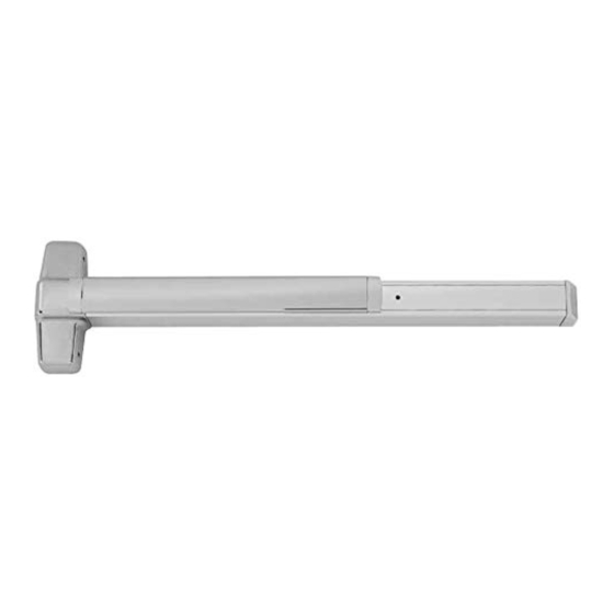
Concealed Vertical Device for Wood Doors
NOTE: If door does not have a cutout for
!
cabling inside lock stile, door must be
routed. Refer to 9949 wood door template.
Customer Service
1-877-671-7011
98/9949WDC
1-Point
Latch
(LBL)
www.allegion.com/us
© Allegion 2014
Printed in U.S.A.
24795361 Rev. 04/14-a
Installation Instructions
2-Point
Latch
includes these
additional
parts
Advertisement

Related Manuals for Von Duprin 9849WDC


Summary of Contents for Von Duprin 9849WDC
- Page 1 FOR DEVICES SOLD PRIOR TO 98/9949WDC 4-14-14 Concealed Vertical Device for Wood Doors Installation Instructions 1-Point 2-Point Latch Latch (LBL) includes these additional parts NOTE: If door does not have a cutout for cabling inside lock stile, door must be routed.
-
Page 2: Cable Removal
Identify Cables and Locations. CABLE IDENTIFICATION (STANDARD SIZES) WOOD DOORS Door Opening NOTE: Cables A and B are red. Cable C is white Height 6' 8" 24078495 23925761 24078453 NOTE: Cables B is 6" longer than Cable A. 7' 0" 23925787 23925720 24078453... - Page 3 Temporarily Attach Bottom Latch Cable Assembly Adjust Bottom Latch Retraction (if necessary). to Center Slide. For 2-Point Latch Only For 2-Point Latch Only NOTE: Adjustment must be made while the top latch is in the hold-open position, with cable flexed into an L-shape to simulate the installed condition of the latches.
- Page 4 Disconnect Bottom Latch Cable Assembly from With Door Laying Flat, Draw Horizontal and Vertical Center Slide. Device Center Lines ( For 2-Point Latch Only RHR shown (LHR opposite) Disconnect cable end A cable removal tool has been NOTE: Centerlines from cable link provided.
- Page 5 If Necessary, Prepare Door Cutouts. Prepare 2 Center Slide Holes. Device Device ¹³⁄₁₆" 1¹⁄₂" 1⁵⁄₈" ⁷⁄₈" 1⁷⁄₈" 5⁷⁄₈" Device Device 1³⁄₄" 39⁵⁄₈" 1⁷⁄₈" to finished ¹⁄₂" Dia. floor (Omit for 2¹⁵⁄₁₆" EO, DT, & TL) 3³⁄₄" ³⁄₁₆" Dia. ³⁄₈" ³⁄₄" 2¹⁄₂"...
- Page 6 Prepare 4 Holes. Assemble Latch Mounting Bracket(s). Install this bracket for 1/4" 3/4" 1/4" Install this bracket for Top Door Channel Bottom For 2-Point Latch Only Install this Surface Mount Sex Bolts or 990 Trims bracket for Install this bracket for Prepare Access Hole for Bottom Latch Adjustment Pin.
- Page 7 Secure Top Latch Mounting Bracket with 3 Screws. If Necessary, Remove NL Drive Screw. NL drive screw Factory installed on back of center case NOTE: It is normal for the cable to bend inside the door, forcing With the NL drive screw removed, key locks and unlocks lever, knob, or the latch outward as thumb piece.
- Page 8 Attach Center Case to Door. Install 2 Center Slide Mounting Screws. Thru-bolting Trim (1³⁄₄" door) (2¹⁄₄" door) Surface Mount Sex Bolts (1³⁄₄" door) Mark and Prepare 2 Holes. (2¹⁄₄" door) Surface Mount Sex Bolts...
- Page 9 Install End Cap Bracket and End Cap. Slide Lower Cable / Bottom Latch Assembly Thru Bottom Latch Housing and into Bottom Door Pocket. For 2-Point Latch Only NOTE: Confirm bottom latch is in correct orientation before proceeding. Bottom Holes should face #10 x 1¹⁄₄"...
- Page 10 Attach Lower Cable Assembly to Center Slide. Prepare Door Frame for Top Strike. For 2-Point Latch Only Edge Latch Reach into door stop pocket to position cable end to bottom mounting Metal bracket ¹⁄₂" Use strike to mark location Wood of 2 holes Push cable snap against bracket to...
- Page 11 Prepare Floor for Bottom Strike. Install Lift Finger and Retainer Clip. For 2-Point Latch Only NOTE: The lift finger installation and adjustment must be performed while the latches are in the extended (latched) position. Pull Side Slide L-shaped lift Insert Latch finger thru block in adjustment...
-
Page 12: Optional Equipment
Perform Functional Test of Door. Adjust Top Strike as Necessary, then Install the Third Strike Screw to Fix the Strike Position. a. Depress pushbar. Door should begin to open when pushbar is nearly fully depressed. If necessary, refer to Step 35 to readjust lift finger. Metal b.
Need help?
Do you have a question about the 9849WDC and is the answer not in the manual?
Questions and answers