Advertisement
VON DUPRIN
Installation Instructions
®
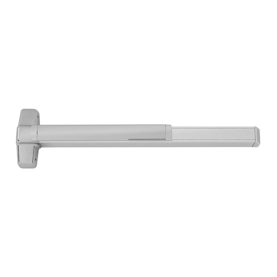
CD98/9947WDC (Cylinder Dogging) Concealed Vertical Rod Device
EL98/9947WDC (Electric Latch Retraction) Concealed Vertical Rod Device
Please give these instructions to building owner after device is installed
This product is covered by the
following patent numbers:
3,767,238
3,854,763
4,167,280
®
98/9947WDC
Wood Door
Devices covered by these instructions:
98/9947WDC Concealed Vertical Rod Device
98/9947WDC-F (Fire) Concealed Vertical Rod Device
Special tools needed:
5/64" hex wrench
#10-24 tap
Drill bits: #25, 1/8", 1/4",
5/16", 13/32"
4,427,223
4,466,643
4,741,563
Concealed Vertical Rod Exit Device
Applications
• Screw chart ............................ 2
• Device installation ................ 3-5
• Door preparation chart ............ 6
• Door routing instructions ......... 7
• Frame preparation chart ......... 8
• Adjust rods ............................. 9
• Optional equipment .......... 10-11
• Cut device ............................ 12
Index:
FAX version 911377_00(3) Page 1 of 12
Advertisement


Need help?
Do you have a question about the Quiet One 9847WDC and is the answer not in the manual?
Questions and answers