Advertisement
Quick Links
Description
The 1141 Emergency Wall Button is a one-button wireless emergency
transmitter designed to be wall-mounted. When pressed, an
emergency message is sent to the EM20 Base Unit and a phone call
is placed to the Central Station. The 1141 also provides an LED that
can be programmed to provide visual indication that a panic alarm
has been transmitted. The 1141 operates using the supplied 3.0VDC
lithium batteries.
Compatibility
All DMP 1100 Series Wireless Receivers and Panels
What is Included
The 1141 Emergency Wall Button includes the following:
• One 1141 Emergency Wall Button
• Two 3.0V lithium CR2430 Batteries
• Hardware pack
• Zone name and number label
• Serial number label
Transmitter Serial Number
For your convenience, an additional pre-printed serial number label
is included. Prior to installing the device, record the serial number
or place the pre-printed serial number label on the panel programming sheet. This number is required during
programming. As needed, use the zone name and number label to identify a specific transmitter.
Programming the Transmitter in the Panel
Program the device as a zone in Zone Information during panel programming. At the Serial Number: option, enter
the eight-digit serial number.
At the LED Operation option select YES to turn the LED ON when an emergency signal is transmitted and
acknowledged by the receiver. The LED pulses for five minutes after the acknowledgement is received from the
wireless receiver. Select NO if you do not want the LED to turn ON when a panic signal is transmitted. The panel
programming default is YES. The LED always provides a single flash to indicate good communication with the 1100
Series receiver when any signal is sent.
Note: When a receiver is installed, powered up, or the panel is reset, the supervision time for transmitters is reset.
If the receiver has been powered down for more than one hour, wireless transmitters may take up to an additional
hour to send a supervision message unless tripped, tampered, or powered up. This operation extends battery life for
transmitters. A missing message may display on the keypad until the transmitter sends a supervision message.
LED Status Operation
The Status LED turns on to acknowledge a button press. See Figure 2.
Mounting the Transmitter
These instructions cover installing the housing on an interior wall.
Figures 3 and 4 show the housing inside and outside views.
1. Install two 1/2" wide strips of double-sided tape in the
indentions on the back of the base housing.
2. Remove the backing from the tape and place the housing in the
desired location on the wall with the LED toward the top. See Figures 3 and 5.
Inst alla tIon GuIde
1141 Emergency Wall Button
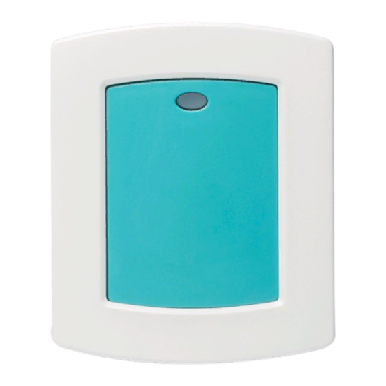
Figure 1: 1141 Emergency Wall Button
Figure 2: Status LED
Advertisement

Related Manuals for DMP Electronics 1141


Summary of Contents for DMP Electronics 1141
-
Page 1: What Is Included
When pressed, an emergency message is sent to the EM20 Base Unit and a phone call is placed to the Central Station. The 1141 also provides an LED that can be programmed to provide visual indication that a panic alarm has been transmitted. - Page 2 Risk of fire, explosion, and burns. Figure 6: Removing the Cover Battery Life Expectancy Typical battery life expectancy for DMP Model 1141 wireless transmitters is 4 years. DMP wireless equipment uses two-way communication to extend battery life. The following situations can reduce battery life expectancy: •...
-
Page 3: Fcc Information
L’exploitation est autorisée aux deux conditions suivantes : (1) l’appareil ne doit pas produire de brouillage, et (2) l’utilisateur de l’appareil doit accepter tout brouillage radioélectrique subi, même si le brouillage est susceptible d’en compromettre le fonctionnement. Digital Monitoring Products 1141 Installation Guide... -
Page 4: Specifications
Specifications Patents Battery U. S. Patent No. 7,239,236 Life Expectancy 5 years (normal operation) Listings and Approvals Type 3.0V lithium CR123A FCC Part 15 Registration ID CCKPC0155 See Battery Life Expectancy for full details. Industry Canada Registration ID 5251A-PC0155 Frequency Range: 903-927 MHz Dimensions Transmitter Case 3.3”...
Need help?
Do you have a question about the 1141 and is the answer not in the manual?
Questions and answers