Table of Contents
Advertisement
Quick Links
1135 SERIES WIRELESS SIREN
Installation Guide
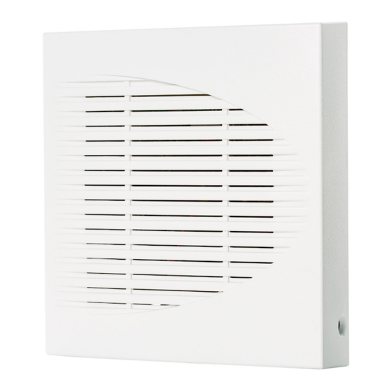
DESCRIPTION
The 1135 Series Wireless Siren
provides up to 110 decibels of
annunciation. It includes a wall
tamper, a cover tamper, and a
Survey LED.
Multiple sirens can be activated
simultaneously by the panel using
the Trip with Panel Bell option. This
option allows the siren to follow the
panel bell output including the bell
cutoff time.
In addition to these features, the
1135E Wireless Siren communicates
with the panel using 128‑bit AES
encryption.
Compatibility
•
All DMP 1100 Series Wireless
Receivers and burglary panels
What is Included?
•
One 1135 Series Wireless Siren
•
Two 3.0 V Lithium CR123
Batteries
•
Hardware Pack
1
PROGRAM THE PANEL
To program the 1135 Series into the panel, select one of the
following methods: Choose Method 1 to make the siren a non‑
standard output that follows the panel bell or Method 2 to make
the siren a standard output.
A house code must be programmed in the panel's SYSTEM
OPTIONS before programming wireless devices. Range is 1 ‑ 50.
For 1135E encrypted sirens to communicate with the panel, 1100
ENCRYPTION must be enabled and a passphrase must be set in
SYSTEM OPTIONS programming.
To enter panel programming, reset the panel and enter 6653
(PROG) at a keypad. After completing each of the following
steps, press CMD to advance to the next prompt. After you finish
programming, go to STOP and press CMD to save and exit the
Programmer menu. For more information, refer to the appropriate
panel programming
PANEL MODEL
XR Series
XT Series
XTL Series
Table 1: Valid Output Numbers by Panel Model
Method 1: Non-Standard Output (Follow Panel)
1.
Go to OUTPUT INFO (XR Series) or OUTPUT SETUP
(XT and XTL Series).
At OUTPUT NO, enter the output number. Refer to
2.
3.
At OUTPUT NAME, enter a descriptive name for the siren.
4.
At SERIAL#, enter the 8‑digit device serial number.
5.
At SUPRVSN TIME, enter the supervision time in minutes.
Ensure TRIP WITH PANEL BELL is set to YES (default).
6.
Go to BELL OPTIONS and set the BELL CUTOFF. Range is
7.
1 ‑ 15 minutes.
Method 2: Standard Output (Standalone)
Go to OUTPUT INFO (XR Series) or OUTPUT SETUP
1.
(XT and XTL Series).
2.
At OUTPUT NO, enter the output number. Refer to
3.
At OUTPUT NAME, enter a descriptive name for the siren.
At SERIAL#, enter the 8‑digit device serial number.
4.
At SUPRVSN TIME, enter the supervision time in minutes.
5.
6.
At TRIP WITH PANEL BELL, select NO.
guide.
VALID OUTPUT NUMBERS
450‑474 (slow) or 480‑499 (fast)
31‑34 (slow) or 41‑44 (fast)
51‑54 (slow) or 61‑64 (fast)
Table
1.
Table
1.
Advertisement
Table of Contents

Related Manuals for DMP Electronics 135 Series


Summary of Contents for DMP Electronics 135 Series
- Page 1 1135 SERIES WIRELESS SIREN Installation Guide PROGRAM THE PANEL To program the 1135 Series into the panel, select one of the following methods: Choose Method 1 to make the siren a non‑ standard output that follows the panel bell or Method 2 to make the siren a standard output.
- Page 2 INSTALL THE BATTERIES Observe polarity and install both CR123 batteries. For the Mounting Holes Wall Tamper battery holder location, refer to Figure PCB Snaps Case Tamper Switch Batteries Survey LED Sound Level SELECT A LOCATION The 1135 Series Wireless Siren provides a Survey LED capability to allow one person to confirm communication with the wireless receiver or panel while the cover is removed.
- Page 3 TEST THE SIREN After the siren has been installed, test to confirm that it is communicating reliably with the panel. Use the Tech APP™ or Dealer Admin™ to perform a Wireless Check‑in Test on the system. To perform a Wireless Check‑in Test from a keypad that is connected to the panel, complete the following steps: At the keypad, enter 8144 (WALK) and select WLS.
- Page 4 FCC INFORMATION This device complies with Part 15 of the FCC Rules. Operation is subject to the following two conditions: This device may not cause harmful interference, and this device must accept any interference received, including interference that may cause undesired operation. The antenna used for this transmitter must be installed to provide a separation distance of at least 20 cm (7.874 in.) from all persons.
Need help?
Do you have a question about the 135 Series and is the answer not in the manual?
Questions and answers