Advertisement
Quick Links
Advertisement

Related Manuals for AMC iA480X


Summary of Contents for AMC iA480X
- Page 1 User iA480X Manual Power amplifier...
- Page 2 RISK OF ELECTRIC SHOCK with liquids, such as vases, shall be placed on the apparatus. DO NOT OPEN USER MANUAL iA480X Power amplifier...
-
Page 3: Table Of Contents
Before you start Controls and connectors Introduction ..............................2 Connectors ................................8 Features ................................2 Cable wiring examples .........................8-9 Operation Specifications Front panel ................................3 Rear panel..............................3-4 General specifications ..........................10 Front panel operation ..........................5 Rear panel operation ..........................6 Output terminal .............................7 USER MANUAL iA480X Power amplifier... -
Page 4: Connectors
Used in a medium and large public address or voice evacuation systems. FEATURES • Balanced phoenix inputs • Phoenix output connectors • Stereo RCA input • DC 24V external power supply input • Input gain control • DC 24V link connector • LINK output • Power, signal, protect and temp indicators • Ground lift • Power switch cover USER MANUAL iA480X Power amplifier... -
Page 5: Operation
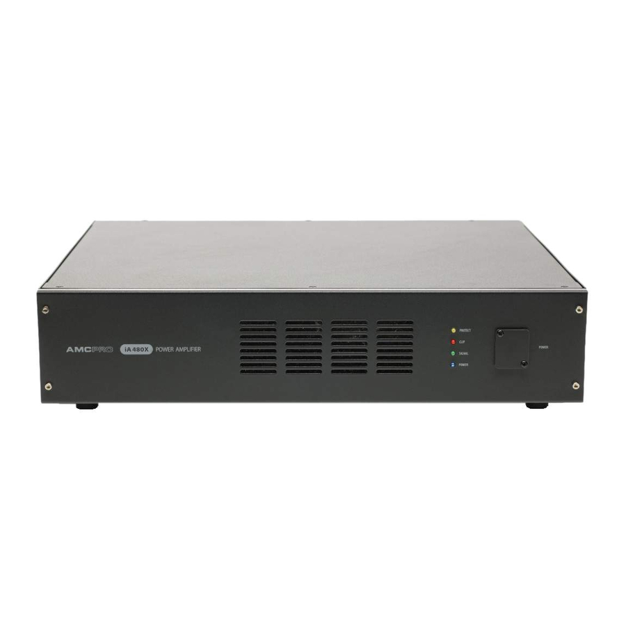
Operation Front Panel 1. Protect indicator | 2. Signal clipping indicator 3. Signal indicator | 4. Power indicator | 5. Power switch USER MANUAL iA480X Power amplifier... -
Page 6: Rear Panel
3. Main power connector 4. Holder for AC fuse | 5. Link for DC 24V power supply | Input for DC 24V power supply 7.Amplifiers output 8. Ground lift switch | 9. Link output | 10. Balanced phoenix and stereo RCA input 11. Input gain control USER MANUAL i iA480X Power amplifier... -
Page 7: Front Panel Operation
HOLDER FOR AC FUSE This LED indicates status of the main power. The LED lights up if the amplifier is powered on. Please use 10A, 250V fuse if amplifier is used in ~230V 50Hz electricity system and 20A, 250V fuse if amplifier is used in ~115V 60Hz system. POWER SWITCH LINK FOR DC 24V POWER SUPPLY Power switch is hided with cover to prevent illegal or incidental use. Remove cover using Phillips screwdriver and use this switch to power on or off the am- This connector is designed to link the DC 24V power to additional amplifier. DC plifier. The power LED in the front panel lights up if the amplifier is powered on. IN and DC LINK connectors are connected with each other directly, inside the amplifier. USER MANUAL iA480X Power amplifier... - Page 8 (0dBu), the Amplifier delivers full power. to connect a ground to amplifiers chassis. LINK OUTPUT Connect outgoing audio signal from stereo RCA and Phoenix connectors to additional amplifier. Input and link connectors are connected with each other directly. USER MANUAL iA480X Power amplifier...
-
Page 9: Output Terminal
Operation Output terminal Amplifiers output can run only one configuration at the same time. Operating amplifiers using 4 Ω and 70 or 100 volt concurrently may cause damage to the amplifier or connected speakers. USER MANUAL iA480X Power amplifier... - Page 10 Cable to unbalanced input from balanced output. TRS and TS connectors. TRS connector Cable to balanced input from unbalanced output. TS and TRS connectors. XLR male connector RCA connector Cable to unbalanced input from unbalanced output. TS connectors. XLR female connector USER MANUAL iA480X Power amplifier...
- Page 11 Cable to unbalanced input from RCA output. RCA and TS connectors. Cable to unbalanced input from balanced output. XLR and TS connectors. Cable to balanced input from RCA output. RCA and XLR connectors. Cable to balanced input from unbalanced output. TS and XLR connectors. Cable to balanced input from RCA output. RCA and TRS connectors. Cable to balanced input from balanced output. TRS and XLR connectors. Cable to RCA input from balanced output. RCA and XLR connectors. RCA cable. Cable to RCA input from balanced output. RCA and TRS connectors. USER MANUAL iA480X Power amplifier...
- Page 12 RF protection, Turn on/Turn off muting. The specifications are correct at the time of printing this manual. For improvement purposes, all specifications for this unit, including design and appearance, are subject to change without prior notice. USER MANUAL iA480X Power amplifier...
Need help?
Do you have a question about the iA480X and is the answer not in the manual?
Questions and answers