Table of Contents
Advertisement
Quick Links
Advertisement
Table of Contents

Related Manuals for AMC iAC 120 DSP


Summary of Contents for AMC iAC 120 DSP
- Page 1 User Manual Installation Power Amplifier...
- Page 2 Safety instructions When using this electronic device, basic precautions Protective Grounding - An apparatus with class I construction shall be connected to a power outlet socket with a protective grounding connection. should always be taken, including the following: Protective Earthing - An apparatus with class I construction shall be connected to a mains socket outlet with a protective earthing connection.
-
Page 3: Table Of Contents
Before you start Introduction ..............................2 Features ................................2 Operation Front/rare panel of iAC 120 DSP ......................3 Front/rare panel of iAC 240 DSP and iAC 360 DSP ..............4 Front/rare panel of iAC 2X240 DSP ....................5 Front panel functions ..........................6 Rear panel functions ...........................7 Main menu ................................7... -
Page 4: Before You Start
Before you start iAC amplifiers with an integrated signal processor are designed for 100 V and low impedance background music systems. The model line consists of single-channel and two-channel amplifiers. They all have an RS 232 control port for integration amplifier with third-party automation systems. Balanced Phoenix and stereo RCA input with audio link connection for easy installation, multiple voltage output suitable for 4 Ω, 70 V, and 100 V speaker lines. -
Page 5: Operation
1. Stereo RCA & balanced Phoenix inputs 2. Link output 3. RS232 serial interface 4. Reset button 5. Main output 6. Main power connector 7. Power and fuse rating: iAC 120 DSP: 220-240V ~50/60Hz 180W Fuse T1.6AL 250V USER MANUAL iAC Installation Power Amplifier... -
Page 6: Front/Rare Panel Of Iac 240 Dsp And Iac 360 Dsp
Operation Front Panel | iAC 240 DSP, iAC 360 DSP 1. Power button 2. LCD display 3. Rotary encoder 4. Signal, limiter & mute indicators Rear Panel | iAC 240 DSP, iAC 360 DSP 1. Stereo RCA & balanced Phoenix inputs 2. -
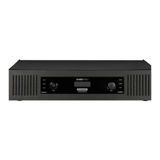
Page 7: Front/Rare Panel Of Iac 2X240 Dsp
Operation Front Panel | iAC 2X240 DSP 1. Signal, limiter & mute indicators 2. Power button 3. LCD display 4. Rotary encoder Rear Panel | iAC 2X240 DSP 1. Stereo RCA & balanced Phoenix inputs 2. Link outputs 3. RS232 serial interface 4. -
Page 8: Front Panel Functions
Operation Front panel functions LED INDICARTORS To jump back from any menu and skip the settings hold the encoder until the LCD THE SIGNAL INDICATOR: illuminates to indicate an audio signal in the amplifier's brings the home screen. (This method does not apply for EQ adjusting.) input. -
Page 9: Rear Panel Functions
Operation Rear panel functions Main menu STEREO RCA & BALANCED PHOENIX INPUTS MENU HOME SCREEN These inputs are designed for line level audio only. Please use a preamplifier to connect a microphone to this amplifier. Pay attention: link output links audio from Phoenix input only, RCA input is not connected to link output. - Page 10 Operation Adjusting EQ: HIGH PASS FILTER → → → To adjust EQ select one of six EQ presets and press rotary encoder. In this setup Amplifier has internal high pass filter to cut off low audio frequencies. This filter amplifier allows to adjust selected EQ gain in +/- 12dB range. After adjusting parameter depends of amplifier output configuration.
- Page 11 Limiter threshold relation with output power (4 Ω output mode) enable or disable this function. Default limiter setting By default audio gate is enabled. The audio gate threshold is fixed to -56dBu. iAC 120 DSP iAC 360 DSP SYNC SETTINGS iAC 240 DSP iAC 2x240 DSP →...
- Page 12 Operation FAN MODE OUTPUT SETUP FOR IAC 2X240 DSP → → → Amplifier cooling is based on fan powered by main CPU. Normally fan rotates at Two channel amplifiers (iAC 2x240 DSP) can be set to 100 V bridge mode to low speed in order to keep air circulation inside amplifier.
-
Page 13: Rs232 Codes | Send Sequences
RS232 COMMANDS Activated standby mode is indicated by the red color LED on the power button. The following table lists commands for IAC 120 DSP / 240 DSP / 360 DSP models. LOCK Amplifier iAC 2x240 DSP uses the same command structure only special bytes to specify the amplifier channel must be sent to control CH1 or CH2 or both channels and ones (Sync mode). - Page 14 Operation RS232 COMMANDS Command Function Control bytes xx Feedback Data bytes xx (CH1 01 CH2 02) MUTE 69 41 43 55 01 02 01 A1 AA 69 41 43 55 01 5D 02 3F AA After unmute amplifier sends 69 41 43 55 01 5D 02 xx AA UNMUTE 69 41 43 55 01 02 01 A0 AA volume level used before mute...
- Page 15 Operation Command Function Control bytes xx Feedback Data bytes xx (CH1 01 CH2 02) HIGH PASS filter direct 69 41 43 55 01 0A 01 xx AA xx – HIGH PASS control bytes 69 41 43 55 02 5D 09 xx AA xx –...
- Page 16 Operation Command Function Control bytes xx Feedback Data bytes xx (CH1 01 CH2 02) xx – EQ point number EQ gain adjust by 69 41 43 55 01 23 01 xx 01 AA xx = EQ point number 69 41 43 55 01 5D 23 xx yy AA yy –...
- Page 17 Operation Command Function Control bytes xx Feedback Data bytes xx (CH1 01 CH2 02) RESET 69 41 43 55 0D 12 01 01 AA 69 41 43 55 0D 5D 12 01 AA 00 = unlock 00 = unlocked 69 41 43 55 0D 11 01 xx AA 69 41 43 55 0D 5D 11 xx AA LOCK/UNLOCK 01 = lock...
- Page 18 Operation GAIN LEVEL control bytes 00 = -12 dB 04 = -8 dB 08 = -4 dB 0C = 0 dB 10 = 4 dB 14 = 8 dB 18 = 12 dB 01 = -11 dB 05 = -7 dB 09 = -3 dB 0D = 1 dB 11 = 5 dB...
- Page 19 Operation LIMITER threshold control bytes 00 = 0 dB 05 = -5 dB 0A = -10 dB 0F = -15 dB 14 = -20 dB 19 = -25 dB 1E = -30 dB 01 = -1 dB 06 = -6 dB 0B = -11 dB 10 = -16 dB 15 = -21 dB...
- Page 20 Operation EQ gain control bytes 00 = -14 dB 03 = -8 dB 06 = -2 dB 0D = 4 dB 0A = 10 dB 01 = -12 dB 04 = -6 dB 07 = 0 dB 0C = 6 dB 09 = 12 dB 02 = -10 dB 05 = -4 dB...
- Page 21 Operation DELAY time control bytes 00 00 = 0 ms 00 48 = 72 ms 00 90 = 144 ms 00 D8 = 216 ms 01 20 = 288 ms 01 68 = 360 ms 01 B0 = 432 ms 00 01 = 1 ms 00 49 = 73 ms 00 91 = 145 ms...
- Page 22 Operation DELAY time control bytes 00 0F = 15 ms 00 57 = 87 ms 00 9F = 159 ms 00 E7 = 231 ms 01 2F = 303 ms 01 77 = 375 ms 01 BF = 447 ms 00 10 = 16 ms 00 58 = 88 ms 00 A0 = 160 ms...
- Page 23 Operation DELAY time control bytes 00 1E = 30 ms 00 66 = 102 ms 00 AE = 174 ms 00 F6 = 246 ms 01 3E = 318 ms 01 86 = 390 ms 01 CE = 462 ms 00 1F = 31 ms 00 67 = 103 ms 00 AF = 175 ms...
- Page 24 Operation DELAY time control bytes 00 2D = 45 ms 00 75 = 117 ms 00 BD = 189 ms 01 05 = 261 ms 01 4B = 333 ms 01 95 = 405 ms 01 DD = 477 ms 00 2E = 46 ms 00 76 = 118 ms 00 BE = 190 ms...
- Page 25 Operation DELAY time control bytes 00 3C = 60 ms 00 84 = 132 ms 00 CC = 204 ms 01 14 = 276 ms 01 5C = 348 ms 01 A4 = 420 ms 01 EC = 492 ms 00 3D = 61 ms 00 85 = 133 ms 00 CD = 205 ms...
-
Page 26: Specifications
General Specifications iAC Installation Power Amplifier Technical Specifications iAC 120 DSP iAC 240 DSP iAC 360 DSP iAC 2X240 DSP Output power 1 x 120 W 1 x 240 W 1 x 360 W 2 x 240 W Bridged output power... - Page 27 Notes AMC is a registered trademark of AMC Baltic www.amcpro.eu...