Table of Contents
Advertisement
Advertisement
Table of Contents

Related Manuals for Axminster HBS350N


Summary of Contents for Axminster HBS350N
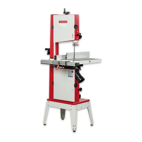
- Page 1 Code 508206 AXMINSTER Hobby SERIES HBS350N 14” Bandsaw...
-
Page 2: Table Of Contents
Index of Contents Index of Contents What’s Included General instructions for 230V Machines 04-05 Specification Unpacking Stand Assembly Mounting the Bandsaw to the Stand Main Assembly 08-09-10-11 Illustration and Parts Description 12-13-14-15-16-17 Setting Up the Saw 18-19-20-21 Operating Instructions Changing the Saw Blade 22-23 Changing the Blade Speed Routine Maintenance... -
Page 3: What's Included
What’s Included Quantity Item Model Number HBS350N 1 No HBS350N 14" Bandsaw (Code: 508206) 1 No Bandsaw Blade 2,490mm long, mounted on saw but not tensioned 1 No Saw Table 1 No Fence Guide Rail 1 No Fence Rear Guide Rail... -
Page 4: General Instructions For 230V Machines
General Instructions for 230 V Machines Keep the machines clean; it will enable you to more Good Working Practices/Safety easily see any damage that may have occurred. The following suggestions will enable you to Clean the machine with a damp soapy cloth if needs observe good working practices, keep yourself and be, do not use any solvents or cleaners as these may fellow workers safe and maintain your tools and... -
Page 5: Specification
Above all, OBSERVE…. make sure you know what very specialised machines for working in these areas, is happening around you and USE YOUR COMMON THIS IS NOT ONE OF THEM. SENSE. Specification Model HBS350N Code 508206 Rating Hobby Power 850W (230V) Blade Speed 600 &... -
Page 6: Unpacking
Unpacking Your saw is packed in the box partially assembled. tip the box up so that the base of the saw is to the This is to ensure that the components are inserted ground, remove all the polystyrene packaging from in the correct positions. -
Page 7: Mounting The Bandsaw To The Stand
Mounting the Bandsaw to the Stand Lift the saw on to the stand, secure using four M8x40 bolts nuts and washers. Insert the bolts through the pre-drilled holes in each corner of the base and through the floor stand. Fit the washers and nuts on the underside and tighten to secure the assembly . - Page 8 Main Assembly Fig 03-04 Mounting the saw table The saw table can be fitted without removing the blade. However, if you would feel more comfortable not having to manoeuvre the table around the blade (the table is quite heavy), remove the blade by open- Stabilising bolt ing the top and bottom covers, release the tension on the blade by backing off the tensioning wheel, see...
- Page 9 Main Assembly Hex bolts and washer (H), see fig 07. Locate the three Fig 10 M8 square head bolts (F), three M8 nuts/washer (G) and the fence guide rail (2). Introduce the square head bolts into the pre-drilled holes to the front of the table (1) and lightly screw on a washer and nut, see fig 08.
-
Page 10: Screwdriver
Main Assembly Check the guide fence is set parallel to the blade. Fig 13 Any slight discrepancy can be taken out by loosening the four Hex bolts that secure the blade of the guide fence to the clamping body, adjust and re-tighten, see fig 16. - Page 11 Main Assembly Step 6 Locate the mitre fence holder (7) and two Phillips screws. Line up the holes in the holder bracket with the pre-drilled holes in the bandsaw pillar and secure in place with the Phillips screws, see fig 19. Locate the mitre fence (8) and slide it into the holder (7), see fig 20.
-
Page 12: Illustration And Parts Description
Illustration and Parts Description Blade tensioning wheel Upper door locking knob Upper wheel door Upper blade guide clamp Mitre fence Upper blade guide & guard Guide fence Saw table ‘T’ slot for mitre fence ON/OFF button and switch shroud Stabilising bolt Fence guide rail Idler wheel adjusting knob Main saw frame... - Page 13 Illustration and Parts Description Table insert plate Insert plate height Fence locking lever (A) adjustment screws Micro adjuster (B) Index marker Lower door lock (A) Mitre fence holder Magnifying glass with index marker Ider wheel adjusting knob (B) ON/OFF NVR switch assembly (A) Mitre fence assembly (A) Stabilising bolt Emergency stop shroud (B)
- Page 14 Illustration and Parts Description Upper saw wheel Upper wheel mounting Table insert Saw table Lower saw wheel Micro door switch Drive pulley...
- Page 15 Illustration and Parts Description Rear thrust bearing (A), Upper bearing blade guides (B) Fore and aft clamping bolt (A) Blade guide bearing adjusting knobs (C) Lateral adjustment clamping grub screws (B) Lower bearing blade guides (A) Blade tensioning spring (A), under tension Lower rear thrust bearing (B) Blade tensioning spring (B) with no tension applied (Guard removed for clarity)
- Page 16 Illustration and Parts Description Fixing holes for fence extension (NOT SHOWN) Table levelling bolt Rear guide rail Optional lifting handle bracket Table clamping handle 100mm Dust extraction Motor Optional mobility wheel...
- Page 17 Illustration and Parts Description Upper door lock (A), Upper blade guide height clamp (B) Fence guide bearing Upper blade guide height adjusting wheel (C), Tracking control knob (D) Tilt quadrant (A), Tilt scale (B), Tilt scale pointer and adjusting screw (C) Table levelling stop bolt (A) (508207) Optional mobility wheel assembly (A) •...
-
Page 18: Setting Up The Saw
Setting Up the Saw Fig 25 DISCONNECT THE SAW FROM THE MAINS SUPPLY! Blade Tensioning and tracking the blade Make sure both top and bottom blade guides are well clear of the blade. Open the front covers fully, giving good access to the Tyre top compartment of the saw and good visibility into the bottom compartment (see page 14). - Page 19 Setting Up the Saw Make sure the upper blade guide is raised as high as possible. Place a square on the table and move it DISCONNECT THE SAW FROM up against the blade (behind the teeth), see fig 32. THE MAINS SUPPLY! Check that the blade is perpendicular to the table.
- Page 20 Setting Up the Saw Setting the Fence Loosen the nut (A) holding the guide assembly in place and adjust the fore and aft position so that To make sure the guide fence is at 90˚line up the the leading edges of the side guide bearings are guide fence with the edge of the table’s ‘T’...
-
Page 21: Operating Instructions
Setting Up the Saw Fig 39-40 Fig 41 Rotate the top wheel by hand, at this point. None of the bearings should come into contact with the blade-only when in use. Re-tighten the nut. Adjust the lower blade guides, and set them similarly to the upper guides, (D ) using an Hex key to release and tighten the clamping bolts. -
Page 22: Operating Instructions
Operating Instructions do not try to cut a 1” radius curve using a 5/8” blade. find something to use as a sacrificial carrier and mount the work piece on it with double sided tape, 8. Make sure the blade is not in contact with the or similar. -
Page 23: Changing The Saw Blade
Changing the Saw Blade Also check that the blade did not “unfold” inside out. Fig 44 i.e. looking at the right side front of the loop, the teeth should be on the front of the blade and pointing down. If you can’t arrive at this view, turn the blade inside out from its current position and look again. -
Page 24: Changing The Blade Speed
Changing the Blade Speed wheel adjusting knob anti-clockwise, thus moving the , see figs 49-50. With the drive belt idler wheel back DISCONNECT THE SAW FROM tension removed, very carefully reposition the drive THE MAINS SUPPLY! belt, see fig 51. NOTE: Make sure the belt is seated correctly in one of the drive pulley grooves. -
Page 25: Routine Maintenance
Routine Maintenance Daily Monthly • Keep the machine clean. • Open the lower and upper door and check the condition of the tyres and the drive belt, see figs • Check the saw blade for missing teeth and 53-54. cracks, see fig 53. •... - Page 26 Parts Breakdown/List...
- Page 27 Parts Breakdown/List Description Q’TY Thin nut M22X1.5 Countersunk head screws M6X16 Lifter wheel Washer ø6 Semicircle head screw M5×8 Nut M6 The connecting nut plate Hinge Switch KJD12 Hinge plate Semicircle head screw M4×10 Knob sleeve Upper wheel Knob screw Axle pressure Nut M5 Bearing...
- Page 28 Parts Breakdown/List Washer ø10 Washer Wave wheel Six angle locking nail M5X10 Elastic cylindrical pin M3X20 Big Washer ø8 Motor Wave hand Knob Locking plate The knob shaft Carriage bolt M8×20 The dust cover Upper blade guard Six countersunk head screws M6 Sliding plate Dead plate Tapping screw M5X10...
- Page 29 Parts Breakdown/List The table is rotating frame T shaped handle M10 Take Semicircle head screw M8×60 The work table fixed seat Six angle locking nail M6X10 Side guards Table pointer Continues Over...
- Page 30 Parts Breakdown/List...
- Page 31 Parts Breakdown/List Description Q’TY Screw guide Fence “L” shape End cap, fence carrier Carriage screw M6x70 Screw guide Six countersunk head screws M6 Lock plate Bushing bearing Pan head screw M4x10 Fence Hex nut M8 Hexagon nut M5 Lock handle, fence Washer ø5 T-nut M5 Bearing bar...
- Page 32 Parts Breakdown/List...
- Page 33 Parts Breakdown/List Description Q’TY Hex bolt M8X16 Support parts Nut M8 Washer ø8 Rubber legs M8X15 Connected plate (1) Connected plate (2)
-
Page 34: Wiring Diagram
Wiring Diagram... -
Page 35: Blades/Accessories
1/2” 508247 1/2” 508248 3/4” 508249 Axminster Hobby Series HBS310 & 350N Wheel Kit An optional wheel kit to provide mobility for the Axminster Hobby Series HBS310N and HBS350N bandsaws. Includes a bolt-on handle for the bandsaw frame. Code HBS310 & 350N Mobility Kit... - Page 36 Hobby, Trade, Industrial, Engineer, Air Tool & Axcnc Technology Series machines It’s probably the most comprehensive FREE guarantee ever- buy with confidence from Axminster! So sure are we of the quality, we cover all parts and labour free of charge for three years! •...
Need help?
Do you have a question about the HBS350N and is the answer not in the manual?
Questions and answers