Table of Contents
Advertisement
For the qualified installer
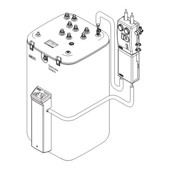
ROTEX Solaris RPS3 P2
Pressurised solar system
Operating and installation manual
Valid for the following components
ROTEX Solaris unit version from 3.0
Solaris R3P differential temperature control system
Sanicube Solaris and HybridCube storage tank
Serial number
Customer
GB
Issue 06/2012
S a
n i c
S o
u b
l a r
e
i s
Advertisement
Table of Contents

Subscribe to Our Youtube Channel
Related Manuals for Rotex Solaris RPS3 P2


Summary of Contents for Rotex Solaris RPS3 P2
- Page 1 ROTEX Solaris RPS3 P2 Pressurised solar system Operating and installation manual Valid for the following components Issue 06/2012 ROTEX Solaris unit version from 3.0 Solaris R3P differential temperature control system Sanicube Solaris and HybridCube storage tank Serial number Customer...
- Page 2 The legal guarantee conditions fundamentally apply. Our warranty conditions beyond that can be found online on your sales presentative's webpage. Declaration of conformity for the Solaris RPS3 P2 pressurised solar system used in conjunction with pressure station RDS1. We, ROTEX Heating Systems GmbH, declare under our sole responsibility that the products Product Order No.
-
Page 3: Table Of Contents
Burner inhibit contact ................37 FA ROTEX Solaris RPS3 P2 - 06/2012... - Page 4 List of keywords ................51 FA ROTEX Solaris RPS3 P2 - 06/2012...
-
Page 5: Safety
Relevant documents The documents listed below are a part of the technical documentation of the ROTEX solar system and must also be taken into consideration. The documents are included in the scope of supply. – Domestic hot water storage tank (ROTEX Sanicube, HybridCube, GasSolarUnit): operating and installation instructions. -
Page 6: Avoid Danger
Avoid danger ROTEX solar systems are constructed to the state of the art and recognised laws of technology. However, improper use may result in serious physical injuries or death, as well as property damage. To avoid any danger, only install and operate your ROTEX solar system: –... -
Page 7: Product Description
Solar flow line (top of solar panel) Thermostatic mixer valve (consumer-side Zone with water for domestic use Accessories scalding protection) Solar zone Fig. 2-1 Standard installation of a ROTEX solar system (ROTEX recommends the two-way connection) FA ROTEX Solaris RPS3 P2 - 06/2012... -
Page 8: Brief Description
As soon as the solar panels have reached a useful temperature level, the liquid in the panel system is pumped through the pressure station and the plate heat exchanger. The feed pump of the Solaris RPS3 P2 control and pump simultaneously pumps the unpressurised buffer water in the domestic hot water storage tank through the plate heat exchanger where it absorbs the heat given off by the solar panel circuit. - Page 9 For hydraulic connection of the RPWT1 plate heat exchanger to the unpressurised tank circulation system of the hot water storage tank. Consists of: – Connection fittings. – Insulated VA 15 solar / VA 18 solar-solar pipe. Fig. 2-5 APWT1 connector kit FA ROTEX Solaris RPS3 P2 - 06/2012...
-
Page 10: Accessories
MAG S 25 ( 16 20 50) MAG 25 MAG 35 For ROTEX Solaris pressure systems with up to 3 solar panels. – Diaphragm expansion vessel 25 l. – Cap valve, connector pipe, installation material. MAG S 35 ( 16 20 51) For ROTEX Solaris pressure systems with up to 5 solar panels. -
Page 11: Installation
System concepts Installation ROTEX solar systems are normally installed in accordance with the system concepts shown in the following. This also includes the possibility of connection on the opposite side of the flat solar panels in each case. The high-output flat solar panels can be mounted on different types of roofs. For more information on installation of solar panels see: –... - Page 12 9. Install press-fit elbow (Ø 22/Ø 18 mm). 10. Prepare feed line (VA 15 Solar) with sensor cable and return line (VA 18 Solar). Cut open the twin heat insulation in the middle. FA ROTEX Solaris RPS3 P2 - 06/2012...
- Page 13 • The pipe should be fixed to a rigid structure (e.g. profile rail, pipe etc.). • Always make sure that pipe runs have a continuous gradient of at least 2 %. FA ROTEX Solaris RPS3 P2 - 06/2012...
-
Page 14: Installing Pressure Station
• Connect feed and return line from the solar panels to connections (4) and (5) on the RDS1 pressure station in accordance with the system plan (see chapter 3.1). • Connect diaphragm expansion vessel (MAG) to the connection (7) on the RDS1 pressure station. FA ROTEX Solaris RPS3 P2 - 06/2012... -
Page 15: Installing Plate Heat Exchanger
• Connect feed and return line from RDS1 pressure station to connections (2) and (3) on the RPWT1 plate heat exchanger. • Flow and return line (VA 15 Solar / VA 18 Solar), install from Solaris RPS3 P2 control and pump unit and domestic hot water storage tank to plate heat exchanger. -
Page 16: Electrical Connection
2. Disconnect the junction box of the domestic electrical installation. 3. Remove cover on switch casing of solar panel circulation pump. 4. Install control line from solar panel circulation pump to Solaris RPS3 P2 control and pump unit. 5. Connect control line to solar panel circulation pump. - Page 17 Fig. 3-24 Work step 3 Automatic speed control of the Solaris RPS3 P2 control and pump unit only works if a FlowSensor has been integrated into the system. Otherwise the tank circulation pump will operate at 100 %. Fig. 3-25 Basic cabling: Storage tank, return flow, solar panel Fig.
-
Page 18: Installing Temperature Sensor
3. Align storage tank sensor in the probe tube to approx. 70 cm insertion depth (cable ties). 4. Insert the plug in the probe tube and lay the cable. Fig. 3-38 Work step 4 FA ROTEX Solaris RPS3 P2 - 06/2012... -
Page 19: Accessories
0 and 20 l/min (flow volume) and 0 to 120 °C (feed temperature). The measured values are shown in the display of the Solaris RPS3 P2 control and pump unit. Thanks to the speed control of the tank circulation pump, the Solaris RPS3 P2 control and pump unit automatically adjusts the passing flow during operation. -
Page 20: Installing Flowguard
– The solar return flow from the RPWT1 plate heat exchanger comes from the solar zone of both storage tanks via the return flow connection line (image 3-43, item 5). – Common return flow is pumped to the RPWT1 plate heat exchanger via the Solaris RPS3 P2 control and pump unit (image 3-43, item 4). - Page 21 200 mm. 4. Preparing the storage tank connecting angle to the Solaris RPS3 P2 control and pump unit. Do so by removing the retaining bracket on the expansion side and remove the ball cock or blanking plug, depending on previous installation.
- Page 22 Installation ROTEX SCS, GSU Solaris RPS3 P2 control and pump unit Solaris - flow manifold Connecting T-piece AGL Compensation line ( 16 01 07) CON SX A Storage tank extension set (bottom) CON SX B Storage tank extension set (top)
-
Page 23: Start-Up And Taking Out Of Service
This may damage system components. • Conduct all work on the components of the solar system only with the solar panels covered. • Only rinse and fill solar system with the prescribed heat exchanger fluid (e.g. ROTEX Solarfluid CORACON SOL 5F, 16 20 52). - Page 24 6. Connect return flow hose to lower filling and draining cock (see also item 9, image 3-14) of RDS1 pressure station and guide into fill container, from which the ROTEX Solarfluid CORACON SOL 5F solar fluid is filled in the solar panel circuit.
-
Page 25: Filling Storage Tank Circuit (System Without Flowsensor)
• Set the measured time plus 5 s in the parameter "Time PsE" (see chapter 5.3.6). 10. Switch Solaris RPS3 P2 control and pump unit to Automatic mode by pressing both arrow keys down at the same time or by performing another switch on/switch off. The system is now ready for operation. -
Page 26: Filling Storage Tank Circuit (System With Flowsensor)
(actuate "Flow" measuring point with arrow keys). 8. Switch Solaris RPS3 P2 control and pump unit to Automatic mode by pressing both arrow keys down at the same time or by performing another switch on/switch off. -
Page 27: Taking Out Of Service
• Disconnect the Solaris RPS3 P2 control and pump unit from all electrical connections and hydraulic connections. • Uninstall the Solaris RPS3 P2 control and pump unit as shown in the installation instructions (chapter 3 "Installation") but in the reverse order. -
Page 28: Operation
Operating and display components for the R3P control systems Operation of control systems Due to continuous improvements for optimum use of the Solaris RPS3 P2 control and pump unit, the Solaris R3P control has been fitted with an update function. Therefore, some functions described in this chapter are applicable to specific software versions only. -
Page 29: Switch-On Lock-Out Function
– cycling of the system can be minimised. – the solar panels can reach a higher temperature. – the feed temperature during filling the system does not fall below the cut-out condition and the system regulates itself faster. FA ROTEX Solaris RPS3 P2 - 06/2012... -
Page 30: Manual Operation
The maximum and calculated values can be shown on the display (see chapter 5.3). Values greater than "0" that have not been deleted will continue to be displayed even after removal or deactivation of the FlowSensors (without further updates). FA ROTEX Solaris RPS3 P2 - 06/2012... -
Page 31: Speed Control Of The P1 Tank Circulation Pump
Solar circuit flow Minimum flow in start phase ("VS min") Minimum flow in operating phase ("S flow") Fig. 5-4 Example for modulation operation with flow-caused block of low pump stages on systems with FlowSensor FA ROTEX Solaris RPS3 P2 - 06/2012... -
Page 32: Global Reset Function
After three fault signals in succession both pumps switch off permanently and the fault signal "F" is shown in the left column of the display. • Replace faulty sensor or eliminate leak. • Start system manually. FA ROTEX Solaris RPS3 P2 - 06/2012... -
Page 33: Setting And Menu Operation
0 to 100 % (see image 5-9) Runtime of tank circulation Only available with technician access Stage on 0 to 99999h pump P1 (see image 5-9) Table 5-3 Maximum values and calculated values FA ROTEX Solaris RPS3 P2 - 06/2012... -
Page 34: Start Display
Then use the arrow keys to scroll up (+ pushbutton) or down (– pushbutton) in the menu tree. The set value can be modified with the arrow keys. A short press on the arrow key changes the value one step, press and hold to make larger changes. FA ROTEX Solaris RPS3 P2 - 06/2012... - Page 35 "Selection 2/2" and then to the operating display (see image 5-9). The control system now operates immediately with the modified parameter values. The control system always jumps back to the operating mode if no button is pressed for about 10 minutes. Fig. 5-9 Settings menu FA ROTEX Solaris RPS3 P2 - 06/2012...
-
Page 36: Password Input
(starting with 01 for the lowest output) and the activity status. • Set the noise-intensive stage to "no" under the parameter "active". The stage will be skipped during actuation of pump P1. FA ROTEX Solaris RPS3 P2 - 06/2012... -
Page 37: Correction Values For Measuring Points
"TS min" was not reached or was exceeded and after expiry of the defined time "VSBK" Fig. 5-10 For example: function of delay time on triggering the burner inhibit contact FA ROTEX Solaris RPS3 P2 - 06/2012... -
Page 38: Recommended Settings
Informative — Not available The system parameters at start-up must be set individually to the installed system situation and if necessary optimised during operation. In general, the system operates with the factory settings. FA ROTEX Solaris RPS3 P2 - 06/2012... -
Page 39: Additional Settings For Your Solar System
15 K. During operation with pump P1, for example at a return temperature of 50 °C, set the solar panel temperature at 60 to 65 °C. If a heat meter is installed in the building, the flow volume can be set by direct measurement during operation with a pump. FA ROTEX Solaris RPS3 P2 - 06/2012... -
Page 40: Recommended Setting For Supplementary Heating With External Heat Sources Or The Electric Immersion Heater, Burner Inhibit Contact
"VBSK" (see chapter 5.3.9) so the external heat generator does not heat, – if the solar panels generate a minimum heat output or – the storage tank has reached a sufficiently high temperature. FA ROTEX Solaris RPS3 P2 - 06/2012... -
Page 41: Tips For Optimised User Behaviour
If no hot water is used for several days and the storage temperature of the Solaris system does not reach at least 60 °C, for hygiene reasons (Legionella protection) it is periodically heated up to above 60 °C once or draw-off of the stored hot water (25 l) is recommended. FA ROTEX Solaris RPS3 P2 - 06/2012... -
Page 42: Faults And Malfunctions
– The lamp associated with the sensor flashes. – The Solaris R3P control system also automatically intervenes in the operation of the system. All other sensor values remain accessible via the arrow keys. FA ROTEX Solaris RPS3 P2 - 06/2012... -
Page 43: Troubleshooting
• Faults on conducting parts of the Solaris RPS3 P2 may only be carried out by heating specialists who have been authorised and accredited by the electrical utility company (EVU). - Page 44 • Evaluate display in the Solaris R3P control system display. • Detach housing on the Solaris RPS3 P2 control and pump unit and remove the relevant sensor, unclamp where necessary. • Examine the contact positions of the affected sensors, and measure the resistance (or the DC voltage for flow temperature and flow rate sensors) on the sensor end.
-
Page 45: Hydraulic System Connection
95 °C, another gravity brake must be installed in the building. A selection of diagrams of the most common systems is shown below. The arrangements shown are only examples, and are no substitute for careful system planning. For more diagrams see the ROTEX home page. Fig. 7-1... - Page 46 Hydraulic system connection Fig. 7-2 Pressurised solar system with GSU Fig. 7-3 Pressurised solar system with 2 Sanicube Solaris SCS 538/16/0 FA ROTEX Solaris RPS3 P2 - 06/2012...
- Page 47 15 70 52 Outside temperature sensor Supplied with GSU/A1. Cylinder temperature sensor Supplied with GSU/A1BG+ASA1. Heating inflow temperature probe Supplied with GSU/A1. Heating return temperature sensor Mixer circuit flow temperature sensor Accessories 15 60 62 FA ROTEX Solaris RPS3 P2 - 06/2012...
- Page 48 Customer-fitted ventilation slate for roof penetration pipes flow and return flow VA 18 Solar return flow pipe VA 15 Solar inflow pipe Panel row connector CON LCP Solaris solar panel (2x 2 collectors) Fig. 7-4 Alternative solar panel arrangement FA ROTEX Solaris RPS3 P2 - 06/2012...
-
Page 49: Technical Data
CONF Programming socket for software update Return flow temperature sensor P1/P2 Operation and booster pump FlowSensor Collector temperature sensor Fuse Storage tank temperature sensor Burner inhibit contact Power Mains supply Fig. 8-1 Connection assignment FA ROTEX Solaris RPS3 P2 - 06/2012... -
Page 50: Diagrams
3.50 V) Table 8-4 Table of Solaris sensors Diagrams Sensor resistance (PTC, Pt 1000) Temperature Fig. 8-2 Resistance characteristics of Solaris sensors Flow rate Sensor output voltage Temperature Fig. 8-3 Characteristics of FlowSensor FA ROTEX Solaris RPS3 P2 - 06/2012... -
Page 51: List Of Keywords
Storage tank ........5 FA ROTEX Solaris RPS3 P2 - 06/2012... - Page 52 FA ROTEX Solaris RPS3 P2 - 06/2012...
Need help?
Do you have a question about the Solaris RPS3 P2 and is the answer not in the manual?
Questions and answers