Table of Contents
Advertisement
• 7-Day, 5-2-Day, or 5-1-1- Day Programmable
• Configurable for Multiple Systems
• Large Display with Backlight
• Selectable Fahrenheit or Celsius
• Icon Indicator Lights
• Relay Outputs – Minimum Voltage Drop in Thermostat
• Remote Sensor Compatible
• Ideally Suited for:
– Residential (New Construction/Replacement)
– Light Commercial
• Works with two-transformer systems
Installation, Operation & Application Guide
For more information on our complete range of American-made
products, wiring diagrams, troubleshooting tips, and more,
please visit us at www.icmcontrols.com
Programmable Thermostat
with Humidity Control
Auto Changeover
MODE
FAN
SCHEDULE
AUTO
OFF
PM
COOL
Wed
COOL
Dual Power
1
Advertisement
Table of Contents

Related Manuals for ICM Controls I3 1010HR


Summary of Contents for ICM Controls I3 1010HR
-
Page 1: Programmable Thermostat
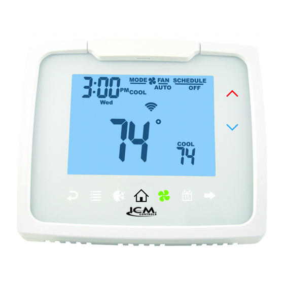
Programmable Thermostat Auto Changeover Dual Power with Humidity Control • 7-Day, 5-2-Day, or 5-1-1- Day Programmable • Configurable for Multiple Systems • Large Display with Backlight MODE SCHEDULE • Selectable Fahrenheit or Celsius AUTO COOL • Icon Indicator Lights • Relay Outputs – Minimum Voltage Drop in Thermostat • Remote Sensor Compatible COOL • Ideally Suited for: – Residential (New Construction/Replacement) – Light Commercial • Works with two-transformer systems Installation, Operation & Application Guide For more information on our complete range of American-made products, wiring diagrams, troubleshooting tips, and more, please visit us at www.icmcontrols.com... -
Page 2: Thermostat Controls
Thermostat Controls MODE SCHEDULE AUTO Up Arrow COOL Down Arrow COOL Left Arrow Right Arrow (Go Back) (Forward) Menu Mode (Heat/Cool) Home Schedule Package Contents/Tools Required Package includes: Thermostat, base, wiring labels, screws and wall anchors, 2 “AA” Alkaline batteries and Installation, Operation and Application Guide Tools required for installation: Drill with 3/16” bit, hammer, screwdriver Specifications Electrical Rating: 24 VAC (18-30 VAC), 1 amp maximum per output terminal, 5 amp maximum total load DC Power: 3.0 VDC (2 “AA”Alkaline batteries) Temperature Control Range: 45°F to 90°F (7°C to 32°C) Accuracy: ±1°F (±0.5°C) Anti-short Cycle: 4 minutes (bypass anti-short cycle delay by returning to OFF mode and pressing the icon). Backlight Operations: 15 seconds Humidity Control: 10% to 80% System Configurations: All may be used with heat pump, gas, oil, electric, and air conditioning • I1010HR: 1-stage heat, 1-stage cool • I2010HR: 2-stage heat, 1-stage cool • I2020HR: 2-stage heat, 2-stage cool... -
Page 3: Important Safety Information
Important Safety Information WARNING!: Always turn off power at the main power supply before installing, cleaning, or removing thermostat. • This thermostat is for 24 VAC applications only; do not use on voltages over 30 VAC. • Do not short across terminals of gas valve or system control to test operation; this will damage your thermostat and void your warranty. • All wiring must conform to local and national electrical and building codes. • Do not use air conditioning when the outdoor temperature is below 50 degrees; this can damage your A/C system and cause personal injuries. • Use this thermostat only as described in this manual. To Remove Existing Thermostat ELECTRICAL SHOCK HAZARD – Turn off power at the main service panel by removing the fuse or switching the appropriate circuit breaker to OFF position before removing the existing thermostat. 1. Turn off power to heating & cooling system by removing the fuse or switching the appropriate circuit breaker off. 2. Remove cover of old thermostat; this should expose the wires. 3. Label the existing wires with the enclosed wire labels before removing wires. 4. After labeling wires, remove wires from wire terminals. 5. Remove existing thermostat base from wall. 6. Refer to the following section for instructions on how to install this thermostat. Battery Installation and Information Two “AA” alkaline batteries are used to power the thermostat. They are installed into the back of the thermostat. -
Page 4: To Install Thermostat
To Install Thermostat ELECTRICAL SHOCK HAZARD – Turn off power at the main service panel by removing the fuse or switching the appropriate circuit breaker to OFF position before removing the existing thermostat. IMPORTANT: T hermostat installation must conform to local and national building and electrical codes and ordinances. Note: Mount the thermostat about five feet above the floor. Do not mount the thermostat on an outside wall, in direct sunlight, behind a door, or in an area affected by a vent or duct. -
Page 5: Terminal Designator Descriptions
Terminal Designator Descriptions SC, S1, S2 – Remote sensor or outdoor sensor RC, RH – 24 VAC hot C – 24 VAC common Y1 – 1st stage cool, 1st stage heat for heat pumps Y2 – Second stage cool for 2-compressor systems. Second stage heat for 2-compressor heat pump systems. G – Fan W 1/O/B – Configurable W1 – 1st stage heat for non-heat pump systems O – Cool active reversing valve B – Heat active reversing valve W2 – 2nd stage heat for 1 compressor heat pump and non-heat pump AUX – Humidifier or dehumidifier Note: Not all terminals are used in every model. -
Page 6: Wiring Diagrams
Wiring Diagrams 1010HR Heating/Cooling 2010HR Heating/Cooling Optional Optional Sensor Common Sensor Common Remote or Remote or Outdoor Outdoor Sensors Sensors Heating Transformer Heating Transformer 120 VAC 24 VAC 120 VAC 24 VAC Cooling Transformer Cooling Transformer 120 VAC 120 VAC Cool/Compressor Cool/Compressor Heat #1/Reversing Valve... - Page 7 Wiring Diagrams (continued) 2020HR Heating/Cooling Optional Sensor Common Remote or Outdoor Sensors Heating Transformer 120 VAC 24 VAC Cooling Transformer 120 VAC Cool/Compressor #1 Heat #1/Reversing Valve Heat #2 Cool/Compressor #2 (de) Humidifier * Remove factory-installed jumper for systems with two transformers. ** Common wire is optional with batteries installed.
-
Page 8: Remote Sensor Installation (Optional)
Remote Sensor Installation (Optional) Terminals S1, S2, and SC are used with remote sensors. S1 can be used with a remote sensor to monitor indoor or outdoor temperatures. An outdoor remote sensor can be used to change system operation based on the outdoor temperature with heat pumps with gas/ oil backup or heat pumps with electric backup. An indoor remote sensor is used to read the indoor temperature in a different location. This is beneficial when the thermostat is not mounted in the ideal location. S2 is a 10kΩ NTC thermistor sensor that can only monitor the temperature in a different area. 1. Remove cover from remote sensor housing. 2. Select an appropriate location for mounting the remote sensors. 3. Mount the remote sensors using hardware provided. Note: Remote or outdoor sensor 4. Install two-strand shielded wire between the S1 terminal on the remote sensor and the S1 terminal on the thermostat. reading can be displayed by 5. Install two-strand shielded wire between the 10kΩ NTC remote sensor and the S2 terminal pressing the icon. on the thermostat. Press , select 6. From both remote sensors, install a two-strand shielded wire from their common to the SC press terminal on the thermostat. 7. Configure the thermostat to work with the remote sensor. Ordering Information: Remote Sensor 1 – Indoor remote sensor: ACC-RT104 – Outdoor remote sensor: ACC-OD104 Remote Sensor 2 – 10kΩ NTC thermistor sensor... -
Page 9: Humidity Output Chart
1010HR Output Chart * G not on for Cool Heat gas/oil systems Heat/Cool Y1, G W1, G* Heat Pump (One Compressor) Y1, G, O Y, G, B 2010HR Output Chart * G not on for Cool Heat Heat gas/oil systems Heat/Cool Y1, G W1, G* W1, W2, G* Heat Pump (One Compressor) Y1, G, O Y1, G, B Y1, G, B, W2 Emergency Heat (Heat Pump Only) W2, G 2020HR Output Chart * G not on for Cool Cool Heat Heat gas/oil systems... -
Page 10: Locking & Unlocking Thermostat
Configuration and Thermostat Lock During Configuration Mode, certain settings are protected by a Write your codes here numeric code access screen to prevent unintentional changes that could potentially damage the system or create a dangerous condition. Whenever changes are attempted to one of the critical settings, the unlock code screen will appear: The unlock code for these critical settings can be found during the power-up sequence. The large number (indicated by “98” in the diagram) is the code that will unlock the desired configuration setting. The smaller numbers (indicated by “93” and “82” in the diagram) are Thermostat lock code codes used to lock and unlock your thermostat to prevent tampering. Configuration safety lock code To view the default codes for your thermostat, remove the thermostat from the sub base and, if using batteries, remove one battery for 10 seconds. Replacing the batteries or reinstalling thermostat will cause the codes to display for approximately 5 seconds. Locking & Unlocking Thermostat To lock and unlock thermostat, perform the following steps: MENU LOCK Press , then , then , then Enter Code Use &... -
Page 11: Changing The Lock Code
Changing the Lock Code To change the lock code, do the following: 1. Press , then press until Lock menu displays. 2. Enter the current lock codes. To find the current lock codes, follow the instructions under “Configuration and Thermostat Lock”. 3. Press to enter new lock codes. 4. Enter new lock codes. 5. Press . The Lock Codes have been updated. Note: Upon subsequent power ups, new lock codes will display. Configuration Mode The configuration mode is used to set the thermostat to match your heating/cooling system. The thermostat functions with heat pump, air conditioning, gas, oil, or electric heat systems. To configure the thermostat, perform the following steps: Press , then press repeatedly until is selected. Press to advance from one screen to the next. Note: Pressing will return you to the previous screen. -
Page 12: Configuration Mode Settings
Configuration Mode Settings The setup screens for Configuration Mode are as follows: 1. Temperature Scale (F or C) Choose Fahrenheit or Celsius. Press the or to select. Press to advance to the next screen. CONFIG 2. 1st Stage Temperature Differential (1°F to 5°F) (0.5°C to 2.5°C) Set the number of degrees between your “setpoint” temperature and your “turn on” temperature. Press the or to set differential value. Press to advance to the next screen. CONFIG 3. 2nd Stage Temperature Differential (1°F to 5°F) (0.5°C to 2.5°C) Note: Not for 1010 Set the number of degrees between when stage 1 turns on and when stage 2 turns on. Press the or to set differential value. Press to advance to the next screen. CONFIG 4. Staged Off Outputs Select whether the outputs for heating and cooling are staged off independently or are satisfied simultaneously. = Outputs off simultaneously. = Outputs staged off independently. CONFIG Press the or to set. Press to advance to the next screen. - Page 13 5. Minimum Deadband (1°F to 9°F) (1°C to 5°C) Set the minimum separation between heat setpoint and cool setpoint in Auto Changeover Mode. Press the or to set deadband value. Press to advance to the next screen. CONFIG 6. Heat Source: There are six heat source settings: WARNING!: Incorrect settings can damage system and/or cause potentially dangerous conditions. Use the code described in Configuration and Thermostat Lock. Non-Heat Pump Heat Pump Electric Heat Pump with Heat Pump with 2 compressors 2 compressors and Heat Active and Cool Active Reversing Valve Reversing Valve CONFIG CONFIG CONFIG CONFIG Heat Pump with Heat Pump with 1 compressor 1 compressor and Heat Active and Cool Active Reversing Valve Reversing Valve CONFIG CONFIG 7. Auxiliary Delay ON (0-60 minutes) Set the delay time in minutes for auxiliary heat to be locked out after a call for second stage. This extra savings feature is used to temporarily lock out auxiliary heat devices, allowing just heat HEAT pump to try to satisfy heat call.
- Page 14 8. Lockout (0-8°, SLEEP, COOL-HEAT) Select the number of degrees set temperature can be changed during keypad lockout. SLEEP setting locks thermostat only during the sleep period to prevent after hours tampering. COOL-HEAT lockout allows adjustment of the set temperatures to the maximum heat set temperature selected and minimum cool set temperature selected. CONFIG Note: The mode cannot be changed while the thermostat is locked. Press the or to select. Press to advance to the next screen. 9. Maximum Heat Setpoint (45°F to 90°F) (7°C to 32°C) Adjust to control the maximum heat set temperature allowed. Press the or to select. Press to advance to the next screen. HEAT CONFIG 10. Minimum Cool Setpoint (45°F to 90°F) (7°C to 32°C) Adjust to control the minimum cool set temperature allowed. Press the or to select. Press to advance to the next screen. COOL CONFIG 11. Vacation Cooling Setpoint These work in conjunction with the Schedule mode where you set the date and time of your VACATION RETURN from vacation (Page 25). Until that date/time, system will remain at the cooling setpoint specified here.
- Page 15 13. Room Temperature Offset (+9°F to -9°F) (+4.5°C to -4.5°C) Adjust to calibrate displayed room temperature to match actual room temperature. Press the or to select. Press to advance to the next screen. CONFIG 14. Maximum Cycles Allowed Per Hour (- -, 2-6) = as many as needed, 2-6 = maximum cycles/hour Press or to select. Press to advance to the next screen. CONFIG 15. Temperature Sensor (L, r, A, r sleep) Note: If there is no remote sensor, option 1 (L) must be selected. May only be used with remote temperature sensor 1. WARNING!: Incorrect settings can damage system and/or cause potentially dangerous CONFIG conditions. Use the code described in Configuration Safety Lock to access this screen setting...
- Page 16 17. Hourly Cycle Fan Operation (1-30 minutes per hour) Used in conjunction with the Fan HOURLY mode. When the user selects this option, the fan will HOURLY turn on at the beginning of every hour and run for the number of minutes indicated here. Press the or to select. Press to advance to the next screen. CONFIG 18. Humidification/Dehumidification (Hu, dE) Set system configuration to work with a humidifier or dehumidifier (including air conditioner). Note: Incorrect settings can damage system and/or cause potentially dangerous conditions. Use the code described in Configuration Safety Lock to access this screen setting. CONFIG Hu: used with a humidifier to humidify home. dE: used with air conditioner or dehumidifier to de humidify home. HUMIDITY Press the or to select. Press to advance to the next screen. 19. Humidity Differential (1% to 10%) Set the percent difference between the setpoint humidity and when the humidifier or dehumidifier system turns on. Press the or to select. Press to advance to the next screen.
- Page 17 21. Extended AC (no, COOL -2 (Fahrenheit), COOL -1 (Celsius)) Note: Only used for Dehumidification when condition is set to COOL-FAN. Set an extended time on the AC to increase dehumidification capabilities. no = No extended AC time. CONFIG COOL -2 or COOL -1 = Cooling system will continue to operate after the set temperature has been reached until the room temperature is 3°F (1.5°C) below the set HUMIDITY temperature if dehumidification has not been satisfied. Press or to select. Press to advance to the next screen. 22. Relay Operation (dehumidification only) Set the relay function to match your system (normally open, normally closed). Press the or to select. Press to advance to the next screen. CONFIG HUMIDITY 23. Fan on Schedule (OFF, WAKE, LEAVE, RETURN, SLEEP) SCHEDULE The fan will run continuously during this scheduled period when the mode is not set to OFF. To turn on the fan during one of the scheduled periods (WAKE, LEAVE, RETURN, SLEEP), please do the following: CONFIG Press the or to select. Press to advance to the next screen.
-
Page 18: Mode Of Operation
25. Reset Check Filter Timer Used to reset the elapsed number of (fan running) hours for the Check Filter Timer RESET Press or to select (YES). Check Filter CONFIG Press to advance to the next screen or press to exit configuration setting mode. Auto exit occurs after two minutes of no icons being touched. Mode of Operation The thermostat is a programmable, manual or auto changeover, up to 2-stage heat (depending on your model) and up to 2-stage cool (depending on your model) thermostat. It functions with air conditioning, heat pumps, gas, oil, or electric heat systems. An outdoor sensor can be used to monitor the ambient temperature. A second remote sensor may be used to monitor the temperature in another area. The thermostat activates the heating appliance when the room temperature is below the set heat temperature (by the differential temperature). When the call for heat has been satisfied, the outputs are turned off. With heat pumps, the thermostat will not let the compressor come on for 4 minutes after it turns off to protect your compressor. When the room temperature is greater than the set cool temperature (by the differential temperature), the cooling device is activated. When the call for cooling has been satisfied, the outputs are turned off. The thermostat will not let the compressor come on for 4 minutes after it turns off to protect your compressor. The program schedule can be overridden by changing the set temperature ( or ). This puts the thermostat into a temporary hold. It will automatically return to the program schedule at the next program schedule transition. This thermostat is also capable of controling a humidifier or dehumidifier. When set to humidification, the thermostat will turn on the humidification system when the relative humidity is lower than the set humidity, by the differential. When the relative humidity reaches the differential humidity set, the thermostat will turn off the humidification system. If the thermostat is controlling a dehumidifier (including an air conditioner), the thermostat will turn on the dehumidifier when the relative humidity is above the setpoint humidity, by the differential. Depending on the settings, when the relative humidity reaches the differential humidity set or the room temperature is 3°F below the set cooling temperature, the dehumidifier is turned off. -
Page 19: Icon Functions
Icon Functions UP – Used to increase the time, set temperatures, and to adjust configuration settings. DOWN – Used to decrease the time, set temperatures, and to adjust configuration settings. MENU – Used to enter configuration, set the clock, lock the thermostat, or select viewing options. CONFIG Sets up thermostat to work for specific systems CLOCK Set year, month, date, and time LOCK Allows you to lock the thermostat to prevent tampering VIEW Allows you to see both the remote sensor temperatures, date, current schedule period, lock screen, filter accumulated time, and show details (system status). HUMIDITY Allows you to view the current relative humidity and change humidity setpoint (10% to 80%). MODE – Used to select between OFF, HEAT, EMERGENCY HEAT (heat pump only), COOL, and AUTO changeover modes. HOME – Wakes thermostat, returns to home screen, and enters changes into memory. FAN – Used to select between AUTO, ON, and HOURLY fan operation. SCHEDULE – Used to edit program schedule, turn program on and off, and set vacation return dates. -
Page 20: Operating Modes
Operating Modes The possible operating modes for the thermostat are: OFF, HEAT, EM HEAT, COOL, and AUTO. Use to select. OFF Mode MODE • In this mode, the thermostat will not turn on the heating or cooling devices Note: The indoor fan can be turned on manually in every operating mode by pressing until displays. The fan icon appears on the display when the fan operates. Heat Mode MODE • In this mode, the thermostat controls the heating system. When the heat outputs, the flame icon HEAT appears on the display for each stage of heat that is on. -
Page 21: Testing The Thermostat
Testing the Thermostat Once the thermostat is configured, it should be thoroughly tested. CAUTION!: Do not energize the air conditioning system when the outdoor temperature is below 50 degrees. It can result in equipment damage or personal injury. Heat Test 1. Press , then press until heat mode is displayed. 2. Adjust the set temperature so it is 5 degrees above the room temperature. 3. Heating should come on within a few seconds. 4. Adjust the set temperature 2 degrees below the room temperature and the heat should turn off. There may be a fan delay on your system. Note: For heat pumps, there is a four-minute delay to protect your compressor after it turns off. To bypass the compressor time delay, go to OFF mode and press Cool Test 1. Press... -
Page 22: Testing The Thermostat Humidity Control
Testing the Thermostat Humidity Control Humidification Test –– when set to humidification, only To test the humidifier, set the mode and fan to the correct setting: HEAT-FAN: Either the heating system or fan must be operating in order for the humidifier to turn on. HEAT: Heat must be operating in order for the humidifier to turn on. no: No condition other than humidity reading below setpoint and differential will turn on humidifier. 1. Go to MENU/HUMIDITY and press 2. Change the humidity setpoint above the relative humidity by the differential (Configuration Menu, Section 19, Page 16). 3. Press twice. You should hear a click and when you go back into the humidity settings you will see ON in the top left corner of the screen. 4. Change the humidity setting below the relative humidity by the differential. The humidifier will turn off. Dehumidification Test –– when set to dehumidification, only To test dehumidification, set the mode and fan to the correct settings. COOL-FAN: Either the cooling system or fan must be operating in order for the dehumidifier to turn on. COOL-no: The cooling system must be turned off in order for the dehumidifier to turn on. no: No condition other than humidity reading above setpoint and differential will turn on dehumidifier. 1. Go to MENU/HUMIDITY and press 2. Change the humidity setpoint below the relative humidity by the differential (Configuration Menu, Section 19, Page 16). 3. Press twice. If the relay configuration is set to normally open, there will be a click and the humidity screen will display ON. If the relay configuration is set to normally closed, the humidity screen will not display ON. 4. Change the humidity setting to greater than the relative humidity by the differential by pressing the 5. Press twice. If the relay configuration is set to normally closed, there will be a click and ON is displayed on the humidity... -
Page 23: Setting The Time And Date
Setting the Time and Date 1. Press , then press until CLOCK is displayed. 8. Press to save value and move to hour. 9. Press or to select the hour. 2. Press to enter date/time setting. Year blinks. 3. Press or to select the year. Note: As you move past 12:00, the AM/PM symbol will change automatically. 4. Press to save value and move to month. 10. Press to save the value and move to minutes. 5. Press or to select the month. 11. Press or to select the minutes. 6. Press to save value and move to day. -
Page 24: View Screen Options
View Screen Options Press , then press repeatedly until the option displays then press Note: These screens are visible when the Press to advance to the next screen. thermostat is locked or unlocked. Press to go to previous screen. View REMOTE SENSOR 1 View program schedule settings SCHEDULE temperature • OFF shows when schedule is off. SLEEP •... -
Page 25: Schedule Override
Display setpoints, fan, and program information = Don’t display setpoints and program schedule information. Press or to select. SLEEP = Always display setpoints and program schedule information. REMOTE SENSOR 1 = REMOTE SENSOR 1 temperature will display. VIEW REMOTE SENSOR 2 = REMOTE SENSOR 2 temperature will display. Press to exit. -
Page 26: Factory Preprogramming
Factory Preprogramming The thermostat comes pre-programmed with the following schedule: MONDAY WAKE 6:00 AM LEAVE 8:00 AM RETURN 6:00 PM SLEEP 10:00 PM thru HEAT 70°F HEAT 62°F HEAT 70°F HEAT 62°F SUNDAY COOL 78°F COOL 85°F COOL 78°F COOL 82°F Troubleshooting Symptom Remedy No display Check for 24 VAC at thermostat; display is blank when 24 VAC is not present. Time and day of week must be reset after power loss with no batteries installed. System fan does not come on properly Verify wiring is correct, check heat source (Gas/Electric) in Configuration (see Section 6, Page 13). No response with first button press Press to activate touch icons. - Page 27 Troubleshooting (continued) Symptom Remedy Heat or Cool not coming on Verify wiring is correct, gently pull on each wire to verify there is a good connection at terminal block. Setpoints do not display all of the time MENU Press six times, VIEW Check for low battery condition or faulty outdoor/remote temperature sensor. displays displays Remote Sensor MENU Check remote sensors temperature at VIEW OVERRIDE displays Program schedule is in temporary override, it will return to schedule at the next transition time. Condensation forming on windows Decrease humidification setting Thermostat says that the humidifier is Check humidifier pad and replace if necessary operating but humidity has not risen Dehumidifier is always running Check the relay configuration (Section 22, Page 17). The room temperature is met, but the air Dehumidification is set to COOL -2. The thermostat will continue to let the conditioner is still operating cooling system operate until the cooling temperature is 3°F below the setpoint or when the dehumidification setpoint is met. Offline ! If the thermostat or APP shows offline ( !) for more than a few minutes, unplug the thermostat from the wall plate, wait one minute, then plug thermostat back into wall plate.
- Page 28 FIVE-YEAR LIMITED WARRANTY The Seller warrants its products against defects in material or workmanship for a period of five (5) years from the date of manufacture. The liability of the Seller is limited, at its option, to repair, replace or issue a non-case credit for the purchase prices of the goods which are provided to be defective. The warranty and remedies set forth herein do not apply to any goods or parts thereof which have been subjected to misuse including any use or application in violation of the Seller’s instructions, neglect, tampering, improper storage, incorrect installation or servicing not performed by the Seller. In order to permit the Seller to properly administer the warranty, the Buyer shall: 1) Notify the Seller promptly of any claim, submitting date code information or any other pertinent data as requested by the Seller. 2) Permit the Seller to inspect and test the product claimed to be defective. Items claimed to be defective and are determined by Seller to be non-defective are subject to a $30.00 per hour inspection fee. This warranty constitutes the Seller’s sole liability hereunder and is in lieu of any other warranty expressed, implied or statutory. Unless otherwise stated in writing, Seller makes no warranty that the goods depicted or described herein are fit for any particular purpose. Patent 6,597,275 – Thermal Intrusion Barrier Patent Pending 14,307,628 – DC Thermostat with Low Battery Response Patent Pending 14,307,650 – DC Thermostat with Latching Relay Repulsing 7313 William Barry Blvd., North Syracuse, NY 13212 (Toll Free) 800-365-5525 (Phone) 315-233-5266...
Need help?
Do you have a question about the I3 1010HR and is the answer not in the manual?
Questions and answers