Table of Contents
Advertisement
• 7-Day, 5-2-Day, or 5-1-1- Day Programmable
• Configurable for Multiple Systems
• Large Display with Backlight
• Selectable Fahrenheit or Celsius
• Icon Indicator Lights
• Relay Outputs – Minimum Voltage Drop in Thermostat
• Remote Sensor Compatible
• Ideally Suited for:
– Residential (New Construction/Replacement)
– Light Commercial
• Works with two-transformer systems
Installation, Operation & Application Guide
For more information on our complete range of American-made
products, wiring diagrams, troubleshooting tips, and more,
please visit us at www.icmcontrols.com
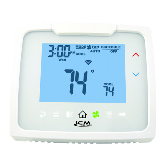
Programmable Thermostat
MODE
FAN
SCHEDULE
AUTO
OFF
PM
COOL
Wed
COOL
Auto
Changeover
1
Advertisement
Table of Contents

Subscribe to Our Youtube Channel
Related Manuals for ICM Controls i3 2010WR


Summary of Contents for ICM Controls i3 2010WR
- Page 1 Programmable Thermostat Auto Changeover • 7-Day, 5-2-Day, or 5-1-1- Day Programmable • Configurable for Multiple Systems • Large Display with Backlight MODE SCHEDULE • Selectable Fahrenheit or Celsius AUTO COOL • Icon Indicator Lights • Relay Outputs – Minimum Voltage Drop in Thermostat • Remote Sensor Compatible • Ideally Suited for: COOL – Residential (New Construction/Replacement) – Light Commercial • Works with two-transformer systems Installation, Operation & Application Guide For more information on our complete range of American-made products, wiring diagrams, troubleshooting tips, and more, please visit us at www.icmcontrols.com...
-
Page 2: Thermostat Controls
Thermostat Controls MODE SCHEDULE MODE SCHEDULE AUTO AUTO Up Arrow COOL COOL Down Arrow COOL COOL Left Arrow Right Arrow (Go Back) (Forward) Menu Mode (Heat/Cool) Home Schedule Package Contents/Tools Required Package includes: Thermostat, base, wiring labels, screws, wall anchors, and Installation, Operation and Application Guide. Tools required for installation: Drill with 3/16” bit, hammer, screwdriver Specifications Electrical Rating: 24 VAC (18-30 VAC), 1 amp maximum per output terminal, 5 amp maximum total load Temperature Control Range: 45°F to 90°F (7°C to 32°C) Accuracy: ±1°F (±0.5°C) Anti-short Cycle: 4 minutes (bypass anti-short cycle delay by returning to OFF mode and pressing the icon). -
Page 3: Mode Of Operation
Mode of Operation The thermostat is a programmable, manual or auto changeover, up to 3-stage heat (depending on your model) and up to 2-stage cool (depending on your model) thermostat. It functions with air conditioning, heat pumps, gas, oil, or electric heat systems. Some thermostats are dual fuel compatible and an outdoor sensor can be used to monitor the ambient temperature. A second remote sensor may be used to monitor the temperature in another area. The thermostat activates the heating appliance when the room temperature is below the set heat temperature (by the differential temperature). When the call for heat has been satisfied, the outputs are turned off. With heat pumps, the thermostat will not let the compressor come on for 4 minutes after it turns off to protect your compressor. When the room temperature is greater than the set cool temperature (by the differential temperature), the cooling device is activated. When the call for cooling has been satisfied, the outputs are turned off. The thermostat will not let the compressor come on for 4 minutes after it turns off to protect your compressor. The program schedule can be overridden by changing the set temperature ( or ). This puts the thermostat into a temporary hold. It will automatically return to the program schedule at the next program schedule transition. To remove the temporary hold before the next schedule transition, press icon twice. The thermostat is also Wi-Fi compatible. After you connect your thermostat to your wireless network, you can monitor and control your thermostat using the app (available for most devices) or a computer connected to the internet. -
Page 4: Icon Functions
Icon Functions UP – Used to increase the time, set temperatures, and to adjust configuration settings. DOWN – Used to decrease the time, set temperatures, and to adjust configuration settings. MENU – Used to enter configuration, set the clock, lock the thermostat, or select viewing options. CONFIG Sets up thermostat to work for specific systems. CLOCK Set year, month, date, and time. WEATHER Shows the highs and lows for three days. LOCK Allows you to lock the thermostat to prevent tampering. VIEW Allows you to see both the remote sensor temperatures, date, current schedule period, lock screen, filter accumulated time, and show details (system status). FAN – Used to select between AUTO, ON, and HOURLY fan operation. MODE – Used to select between OFF, HEAT, EMERGENCY HEAT compressor (heat pump only), COOL, and AUTO changeover modes. HOME – Wakes thermostat, returns to home screen, and enters changes into memory. SCHEDULE – Used to edit program schedule, turn program on and off, and set vacation return dates. ! Flashing – The thermostat is in Setup Mode and is searching for a wireless network. Flashing – Wi-Fi is busy. ! Solid – The thermostat is not connected to Wi-Fi. If the thermostat has successfully connected to Wi-Fi previously, and no new conditions exist (i.e. password change, wireless router change), the thermostat will automatically reconnect— otherwise the thermostat will have to be reconnected to the wireless network manually. Solid – The thermostat is connected to Wi-Fi. Important Safety Information WARNING!: Always turn off power at the main power supply before installing, cleaning, or removing thermostat. • This thermostat is for 24 VAC applications only; do not use on voltages over 30 VAC. • Do not short across terminals of gas valve or system control to test operation; this will damage your thermostat and void your warranty. • All wiring must conform to local and national electrical and building codes. • Do not use air conditioning when the outdoor temperature is below 50 degrees; this can damage your A/C system and cause personal injuries. -
Page 5: To Remove Existing Thermostat
To Remove Existing Thermostat ELECTRICAL SHOCK HAZARD – Turn off power at the main service panel by removing the fuse or switching the appropriate circuit breaker to OFF position before removing the existing thermostat. 1. Turn off power to heating & cooling system by removing the 4. After labeling wires, remove wires from wire fuse or switching the appropriate circuit breaker off. terminals. 2. Remove cover of old thermostat; this should expose the wires. 5. Remove existing thermostat base from wall. 3. Label the existing wires with the enclosed wire labels before 6. Refer to the following section for instructions on removing wires. how to install this thermostat. To Install Thermostat ELECTRICAL SHOCK HAZARD – Turn off power at the main service panel by removing the fuse or switching the appropriate circuit breaker to OFF position before installing new thermostat. IMPORTANT: T hermostat installation must conform to local and national building and electrical codes and ordinances. Note: Mount the thermostat about five feet above the floor. -
Page 6: Terminal Designator Descriptions
Terminal Designator Descriptions SC, S1, S2 – Remote sensor or outdoor sensor RC, RH – 24 VAC hot C – 24 VAC common Y1 – 1st stage cool, 1st stage heat for heat pumps Y2 – 2nd stage cool for 2-compressor systems. 2nd stage heat for 2-compressor heat pump systems. G – Fan W 1/O/B – Configurable W1 – 1st stage heat for non-heat pump systems O – Cool active reversing valve B – Heat active reversing valve W2 – 2nd stage heat for 1 compressor heat pump and non-heat pump AUX – 3rd stage heat Note: Not all terminals are used in every model. -
Page 7: Wiring Diagrams
Wiring Diagrams 1010WR Heating/Cooling 2010WR Heating/Cooling Optional Optional Sensor Common Sensor Common Remote or Remote or Outdoor Outdoor Sensors Sensors Heating Transformer Heating Transformer 120 VAC 24 VAC 120 VAC 24 VAC Cooling Transformer Cooling Transformer 120 VAC 120 VAC Cool/Compressor Cool/Compressor Heat #1/Reversing Valve... - Page 8 Wiring Diagrams (continued) 2020WR Heating/Cooling 3020WR Heating/Cooling Optional Optional Sensor Common Sensor Common Remote or Remote or Outdoor Outdoor Sensors Sensors Heating Transformer Heating Transformer 120 VAC 24 VAC 120 VAC 24 VAC Cooling Transformer Cooling Transformer 120 VAC 120 VAC Cool/Compressor #1 Cool/Compressor #1 Heat #1/Reversing Valve...
-
Page 9: Remote Sensor Installation (Optional)
Remote Sensor Installation (Optional) Terminals S1, S2, and SC are used with remote sensors. S1 can be used with a remote sensor to monitor indoor or outdoor temperatures. An outdoor remote sensor can be used to change system operation based on the outdoor temperature with heat pumps with gas/ oil backup or heat pumps with electric backup. An indoor remote sensor is used to read the indoor temperature in a different location. This is beneficial when the thermostat is not mounted in the ideal location. S2 is a 10kΩ NTC thermistor sensor that can only monitor the temperature in a different area. 1. Remove cover from remote sensor housing. 2. Select an appropriate location for mounting the remote sensors. 3. Mount the remote sensors using hardware provided. Note: 4. Install two-strand shielded wire between the S1 terminal on the remote sensor and the S1 Remote or outdoor sensor reading can be displayed by terminal on the thermostat. 5. Install two-strand shielded wire between the 10kΩ NTC remote sensor and the S2 terminal pressing the icon. on the thermostat. Press , select 6. From both remote sensors, install a two-strand shielded wire from their common to the SC press terminal on the thermostat. 7. Configure the thermostat to work with the remote sensor. Ordering Information: Remote Sensor 1 – Indoor remote sensor: ACC-RT104 – Outdoor remote sensor: ACC-OD104 Remote Sensor 2 – 10kΩ NTC thermistor sensor 1010R Output Chart... - Page 10 2010WR Output Chart Cool Heat Heat Heat/Cool Y1, G W1, G* W1, W2, G* Heat Pump (One Compressor) Y1, G, O Y1, G, B Y1, G, B, W2 * G not on for Emergency Heat (Heat Pump Only) W2, G gas/oil systems 2020WR Output Chart Cool Cool Heat Heat Heat/Cool Y1, G Y1, Y2, G W1, G* W1, W2, G* Heat Pump (One Compressor) Y1, G, O Y1, G, O Y1, G, B Y1, W2, G, B Heat Pump (Two Compressors) Y1, G, O Y1, Y2, G, O Y1, G, B Y1, Y2, G, B * G not on for Emergency Heat (Heat Pump Only) W2, G...
-
Page 11: Locking & Unlocking Thermostat
Configuration and Thermostat Lock During Configuration Mode, certain settings are protected by a Write your numeric code access screen to prevent unintentional changes that codes here could potentially damage the system or create a dangerous condition. Whenever changes are attempted to one of the critical settings, the unlock code screen will appear: The unlock code for these critical settings can be found during the power-up sequence. The large number (indicated by “98” in the diagram) is the code that will unlock the desired configuration setting. The smaller numbers (indicated by “93” and “82” in the diagram) are Thermostat lock code codes used to lock and unlock your thermostat to prevent tampering. Configuration safety lock code To view the default codes for your thermostat, remove the thermostat from the sub base for 10 seconds. Reinstalling thermostat will cause the codes to display for approximately 5 seconds. Locking & Unlocking Thermostat To lock and unlock thermostat, perform the following steps: MENU LOCK Press , then , then , then Enter Code Use &... -
Page 12: Changing The Lock Code
Changing the Lock Code To change the lock code, do the following: 1. Press , then press until Lock menu displays. 2. Enter the current lock codes. To find the current lock codes, follow the instructions under “Configuration and Thermostat Lock”. 3. Press to enter new lock codes. 4. Enter new lock codes. 5. Press . The Lock Codes have been updated. Note: Upon subsequent power ups, new lock codes will display. Configuration Mode The configuration mode is used to set the thermostat to match your heating/cooling system. The thermostat functions with heat pump, air conditioning, gas, oil, or electric heat systems. To configure the thermostat, perform the following steps: Press , then press repeatedly until is selected. Press to advance from one screen to the next. Note: Pressing will return you to the previous screen. -
Page 13: Configuration Mode Settings
Configuration Mode Settings The setup screens for Configuration Mode are as follows: 1. Temperature Scale (F or C) Choose Fahrenheit or Celsius. Press the or to select. Press to advance to the next screen. CONFIG 2. 1st Stage Temperature Differential (1°F to 5°F) (0.5°C to 2.5°C) Set the number of degrees between your “setpoint” temperature and your “turn on” temperature. Press the or to set differential value. Press to advance to the next screen. CONFIG 3. 2nd Stage Temperature Differential (1°F to 5°F) (0.5°C to 2.5°C) Note: Not for 1010W Set the number of degrees between when stage 1 turns on and when stage 2 turns on. Press the or to set differential value. Press to advance to the next screen. CONFIG 4. 3rd Stage Temperature Differential (1°F to 5°F) (0.5°C to 2.5°C) Note: Only for 3020W Set the number of degrees between when stage 2 turns on and when stage 3 turns on. Press the or to set differential value. - Page 14 5. Staged Off Outputs Select whether the outputs for heating and cooling are staged off independently or are satisfied simultaneously. = Outputs off simultaneously (best for dual fuel). = Outputs staged off independently. CONFIG Note: For 2 compressor heat pumps and multi-stage gas/oil systems, stage 3 is staged off independently when SO is set to Press the or to set. Press to advance to the next screen. 6. Minimum Deadband (1°F to 9°F) (1°C to 5°C) Set the minimum separation between heat setpoint and cool setpoint in Auto Changeover Mode. Press the or to set deadband value. Press to advance to the next screen. CONFIG 7. Heat Source: There are six heat source settings: WARNING!: Incorrect settings can damage system and/or cause potentially dangerous conditions. Use the code...
- Page 15 8. *Dual Fuel System ( Appears only if heat pump is selected. For non-heat pump users, please skip this section and advance to the Auxiliary Delay screens on Page 16. CONFIG = Heat pump with gas/oil furnace back up (see below). = Heat pump with gas/oil furnace back up, but furnace can turn on during warm outdoor conditions (see below). = Heat pump with electric backup (see below). Press the or to select. Press to advance to the next screen. Remote Sensor When Used as Outdoor Sensor ( 3020 only) For Heat Pumps With Electric Backup For Heat Pumps With Gas/Oil For Heat Pumps With Gas/Oil (DF = Backup (DF = Backup (DF = When the ambient temperature is above the hen the ambient temperature is hen the ambient temperature is selected temperature, the heat pump will above selected temperature, only above selected temperature, heat operate and electric backup will be locked out. the heat pump will operate. pump operates with auxiliary stage Ambient temperature between the selected of gas or oil heat.
- Page 16 9. Outdoor Upper Setpoint (50°F to 25°F, – –) (10°C to -4.0°C, – –) WARNING!: Incorrect settings can damage system and/or cause potentially dangerous conditions. Use the code described in Configuration Safety Lock. Note: Select upper setpoint for chart on previous page. Select to disable. CONFIG Press the or to select. Press to advance to the next screen. 10. Outdoor Lower Setpoint (select – – to disable) Appears only for heat pump with electric backup with outdoor upper setpoint enabled. Note: Select lower setpoint for chart on previous page. Press the or to select temperature. CONFIG Press to advance to the next screen. 11. Auxiliary Delay ON (0-60 minutes) Set the delay time in minutes for auxiliary heat to be locked out after a call for second stage. This extra savings feature is used to temporarily lock out auxiliary heat devices, allowing just heat pump to HEAT try to satisfy heat call.
- Page 17 14. Minimum Cool Setpoint (45°F to 90°F) (7°C to 32°C) Adjust to control the minimum cool set temperature allowed. Press the or to select. Press to advance to the next screen. COOL CONFIG 15. Vacation Cooling Setpoint VACATION These work in conjunction with the Schedule mode where you set the date and time of your RETURN from vacation (Page 28). Until that date/time, system will remain at the cooling setpoint specified here. COOL CONFIG Press the or to select. Press to advance to the next screen. 16. Vacation Heating Setpoint VACATION These work in conjunction with the Schedule mode where you set the date and time of your RETURN from vacation (Page 28). HEAT Until that date/time, system will remain at the heating setpoint specified here. CONFIG Press the or to select. Press to advance to the next screen. 17. Room Temperature Offset (+9°F to -9°F) (+4.5°C to -4.5°C) Adjust to calibrate displayed room temperature to match actual room temperature. Press the or to select. Press to advance to the next screen. CONFIG 18. Maximum Cycles Allowed Per Hour (- -, 2-6) = as many as needed, 2-6 = maximum cycles/hour...
- Page 18 19. Temperature Sensor (L, r, A, r sleep) Note: If there is no remote sensor, option 1 (L) must be selected. May only be used with remote temperature sensor 1. WARNING!: Incorrect settings can damage system and/or cause potentially dangerous CONFIG conditions. Use the code described in Configuration Safety Lock to access this screen setting. Appears only for non-heat pump systems and heat pumps without an outdoor sensor. 1. L – Only on-board sensor determines room temperature. 2. r – Only remote sensor determines room temperature. 3. A – Average temperature of on-board and remote sensor. 4. r Sleep – Only on-board sensor will be used until SLEEP period, and then only remote sensor is used for SLEEP period. Press the or to select. Press to advance to the next screen. 20. Fan Delay Off Time (0, 30, 60, 90 seconds) Select the amount of time the fan continues to operate after the cool/heat demand has been satisfied. Functions for cooling, heat pumps and electric heat. Press or to select.
- Page 19 23. Check Filter Timer (800-2500 hours) After the number of (fan running) hours specified (for example, 1200 hours), the words “CHECK FILTER” will display to remind you to check/change the system filter. The next configuration screen is Check where the elapsed number of run hours can be reset. Filter CONFIG Press or to select. Press to advance to the next screen. 24. Reset Check Filter Timer Used to reset the elapsed number of (fan running) hours for the Check Filter Timer. Press or to select (YES). RESET Check Filter Press to advance to the next screen. CONFIG 25. Wi-Fi Reset After installation, you will have to reset Wi-Fi on your thermostat to connect to the wireless network for the first time. If you have previously connected the thermostat to the wireless network but have changed your password or installed a new wireless router, you will have to manually reconnect the thermostat to the wireless network as if for the first time. Note: If the thermostat has been connected to a wireless network before, the reset Wi-Fi configuration will be the last screen in the Configuration Menu.
- Page 20 Using an Apple Device 1. Download the app from the Apple App store by searching “ICM i3™ Thermostat”. 2. Reset Wi-Fi on thermostat. To reset Wi-Fi, please follow the steps under Wi-Fi Reset on Page 19. 3. Go to SETTINGS on your Apple device and select Wi-Fi. 4. In the list of available networks; select the network named: ICM_I3_xxxxxxxxxxxx (x’s indicate thermostat ID). A checkmark will appear next to the network when connected. 5. Re-enter the app and follow the prompts to connect your thermostat to the wireless network. Using an Android Device There are three ways to connect your thermostat to the wireless network using the Android app: adding a new thermostat, using the thermostat wireless network, and using a thermostat already listed in your account. Note: Before continuing, download app by searching “ICM i3™ Thermostat” in the app store. 1. Adding a new thermostat: a. Open the app and sign into your account. b. Select “+Add new thermostat”. c. Enter the thermostat ID found on a label affixed to the back of the thermostat above the terminals and on the front of this book.
- Page 21 Using a Computer with Wi-Fi There are two ways to connect your thermostat to your wireless network using a computer with Wi-Fi: using the WPS button on your wireless router or connecting with your wireless network. If you do not remember your wireless password, you can use the WPS button to connect your thermostat to the network. 1. Reset Wi-Fi on thermostat. To reset Wi-Fi, please follow the steps under Wi-Fi Reset on Page 19. 2. Go to Network Settings in Control Panel and select the network named: ICM_I3_xxxxxxxxxxxx (x’s indicate thermostat ID You may also connect to the network by clicking on (Microsoft) or (Apple) and selecting the correct wireless network. 3. In your internet browser, enter http://192.168.10.1/ in the address line. Using Your Wireless Network: a. In the list of available networks, select the correct network and enter password (if password protected). ! will stop flashing and will display, indicating the thermostat is successfully connected to Wi-Fi. Using the WPS Button: a. On your wireless router, press the WPS button until the router indicates it is searching for a wireless device. b. On your computer, scroll to the bottom of the page in the browser and select “Go!” under “Press the WPS button on your Wi-Fi Access Point”. c. ! will stop flashing and will display, indicating the thermostat is successfully connected to Wi-Fi. 4. In your internet browser, enter http://www.captouchwifi.com in the address line. 5. Sign into your account. 6. Under “Add thermostat” enter the thermostat ID, found on a label affixed to the back of the thermostat and on the front of this book.
-
Page 22: Weather Screen
Testing Wi-Fi Connection 1. In the app or through http://www.captouchwifi.com, change fan mode to ON. 2. You will hear a click and see displayed on the thermostat next to fan. Thermostat is successfully connect to the internet. 3. Change the fan mode to the desired setting. Weather Screen The thermostat allows you to see the high and low temperature for three days, as well as the current outdoor temperature and relative humidity for the current day – according to the zip code enetered at the thermostat registration. Press , then press until displays. Press to advance from one screen to the next. Note: Pressing will return you to the previous screen. To exit weather, press Setting the Time and Date 1. Press , then press until CLOCK is displayed. 10. Press to save the value and move to minutes. 2. Press to enter date/time setting. Year blinks. 11. Press or to select the minutes. -
Page 23: Operating Modes
Operating Modes The possible operating modes for the thermostat are: OFF, HEAT, EM HEAT, COOL, and AUTO. Use to select. OFF Mode MODE • In this mode, the thermostat will not turn on the heating or cooling devices Note: The indoor fan can be turned on manually in every operating mode by pressing until displays. The fan icon appears on the display when the fan operates. Heat Mode MODE • In this mode, the thermostat controls the heating system. When the heat outputs, the flame icon HEAT appears on the display for each stage of heat that is on. -
Page 24: Testing The Thermostat
Testing the Thermostat Once the thermostat is configured, it should be thoroughly tested. CAUTION!: Do not energize the air conditioning system when the outdoor temperature is below 50 degrees. It can result in equipment damage or personal injury. Heat Test 1. Press , then press until heat mode is displayed. 2. Adjust the set temperature so it is 5 degrees above the room temperature. 3. Heating should come on within a few seconds. 4. Adjust the set temperature 2 degrees below the room temperature and the heat should turn off. There may be a fan delay on your system. Note: For heat pumps, there is a four-minute delay to protect your compressor after it turns off. To bypass the compressor time delay, go to OFF mode and press Cool Test 1. Press... -
Page 25: Setting The Program Schedule
Setting the Program Schedule The thermostat has four periods (WAKE, LEAVE, RETURN, SLEEP) that are customizable for each day of the week. Each period will have a start time, heat temperature, and cool temperature. The thermostat monitors the day and time, while maintaining the specific conditions you have chosen for each period in your program. Note: You can also set you schedule through the app on your smart device or through http://www.captouchwifi.com Setting the program schedule: 1. Press , then press until EDIT is displayed. 2. Press to enter Program Schedule. 3. The day of the week flashes. Use the or to select the day of the week. Note: You can select the days individually, or if you keep pressing or , there is an option for MON-FRI, MON-SUN or SAT-SUN. -
Page 26: View Screen Options
View Screen Options Press , then press repeatedly until the option displays then press Note: These screens are visible when the Press to advance to the next screen. thermostat is locked or unlocked. Press to go to previous screen. View REMOTE SENSOR 1 View program schedule settings SCHEDULE temperature • OFF shows when schedule is off. SLEEP •... -
Page 27: Schedule Override
Display setpoints, fan, and program information Press or to select. = Don’t display setpoints and program schedule information. SLEEP = Always display setpoints and program schedule information. REMOTE SENSOR 1 = REMOTE SENSOR 1 temperature will display. VIEW REMOTE SENSOR 2 = REMOTE SENSOR 2 temperature will display. Press to exit. -
Page 28: Factory Preprogramming
Factory Preprogramming The thermostat comes pre-programmed with the following schedule: MONDAY WAKE 6:00 AM LEAVE 8:00 AM RETURN 6:00 PM SLEEP 10:00 PM thru SUNDAY HEAT 70°F HEAT 62°F HEAT 70°F HEAT 62°F COOL 78°F COOL 85°F COOL 78°F COOL 82°F Use the following personal program schedule to record your settings: MONDAY WAKE LEAVE RETURN SLEEP HEAT HEAT HEAT HEAT COOL COOL COOL... - Page 29 Personal Program Schedule (continued) FRIDAY WAKE LEAVE RETURN SLEEP HEAT HEAT HEAT HEAT COOL COOL COOL COOL SATURDAY WAKE LEAVE RETURN SLEEP HEAT HEAT HEAT HEAT COOL COOL COOL COOL SUNDAY WAKE LEAVE RETURN SLEEP HEAT HEAT HEAT HEAT COOL COOL COOL COOL...
-
Page 30: Troubleshooting
Troubleshooting Symptom Remedy No display Check for 24 VAC at thermostat; display is blank when 24 VAC is not present. System fan does not come on properly Verify wiring is correct, check heat source (Gas/Electric) in Configuration (see Section 7, Page 14). No response with first button press Press to activate touch icons. Program schedule activates at wrong time Check time (AM/PM) set on thermostat (see Setting the Time & Date, Page 22). Thermostat turns on/off too frequently Adjust temperature differential (see Configuration Mode Setting, Pages 12-13). Thermostat does not follow program Verify the schedule is on : check time (AM/PM); check if in program override. Fan runs continuously Press and set to auto is continuous run. Room temperature is not correct Calibrate thermostat (see Configuration Mode Setting, Section 17, Page 17). If remote sensor is used, check S1 and S2 terminal connections. LOCK displays when any button is Thermostat has the button lockout function activated pressed (see Lockout & Unlock Feature, Page 11). Check for a bad connection at S1 and S2 terminals, if used on display instead of room temperature (see Configuration Mode Setting, Section 19, Pages 18). Heat or Cool not coming on Verify wiring is correct, gently pull on each wire to verify there is a good connection at terminal block. Remote Sensor displays MENU Check remote sensors temperature at VIEW OVERRIDE displays... - Page 31 Troubleshooting (continued) Symptom Remedy Setpoints do not display all of the time MENU Press six times, VIEW Problems connecting using Connect your thermostat using a computer with Wi-Fi. If you are having trouble, the best option is to the app use the WPS button (as described under Using a Computer with Wi-Fi, Page 21). Problem finding app Apple devices require iOS 7.0 or newer software. Android devices require Android Honeycomb (Android version 3.1) or newer software. Offline ! If the thermostat or APP shows offline ( !) for more than a few minutes, unplug the thermostat from the wall plate, wait one minute, then plug thermostat back into wall plate. FCC Compliance Statement (Part 15.19) This device complies with part 15 of the FCC Rules. Operation is subject to the following two conditions: (1) This device may not cause harmful interference, and (2) this device must accept any interference received, including interference that may cause undesired operation. FCC Part 15.21 Statement Modifications or changes made to the device, not approved by the originating party, may void user authority to operate the device. FCC RF Exposure Statement To ensure FCC and Industry Canada compliance, maintain a separation distance of 20 cm from device. Section 7.1.2 of RSS-GEN Under Industry Canada regulations, this radio transmitter may only operate using an antenna of a type and maximum (or lesser) gain approved for the transmitter by Industry Canada. To reduce potential radio interference to other users, the antenna type and its gain should be so chosen that the equivalent isotropically radiated power (e.i.r.p.) is not more than that necessary for successful communication. Conformément à la réglementation d’Industrie Canada, le présent émetteur radio peut fonctionner avec une antenne d’un type et d’un gain maximal (ou inférieur) approuvé pour l’émetteur par Industrie Canada. Dans le but de réduire les risques de brouillage radioélectrique à l’intention des autres utilisateurs, il faut choisir le type d’antenne et son gain de sorte que la puissance isotrope rayonnée équivalente (p.i.r.e.) ne dépasse pas l’intensité nécessaire à l’établissement d’une communication satisfaisante. Section 7.1.3 of RSS-GEN This device complies with Industry Canada license-exempt RSS standard(s). Operation is subject to the following two conditions: (1) this device may not cause interference, and (2) this device must accept any interference, including interference that may cause undesired operation of the device. Le présent appareil est conforme aux CNR d’Industrie Canada applicables aux appareils radio exempts de licence. L’exploitation est autorisée aux deux conditions suivantes : (1) l’appareil ne doit pas produire de brouillage, et (2) l’appareil doit accepter tout brouillage radioélectrique subi, même si le brouillage est susceptible d’en compromettre le fonctionnement.
-
Page 32: Five-Year Limited Warranty
Scan now to download FIVE-YEAR LIMITED WARRANTY the i3 app now! The Seller warrants its products against defects in material or workmanship for a period of five (5) years from the date of manufacture. The liability of the Seller is limited, at its option, to repair, replace or issue a non-case credit for the purchase prices of the goods which are provided to be defective. The warranty and remedies set forth herein do not apply to any goods or parts thereof which have been subjected to misuse including any use or application in violation of the Seller’s instructions, neglect, tampering, improper storage, incorrect installation or servicing not performed by the Seller. In order to permit the Seller to properly administer the warranty, the Buyer shall: 1) Notify the Seller promptly of any claim, submitting date code information or any other pertinent data as requested by the Seller. 2) Permit the Seller For Apple phones For Android phones to inspect and test the product claimed to be defective. Items claimed to be defective and are determined by Seller to be non-defective are subject to a $30.00 per hour inspection fee. 1. Download the app. This warranty constitutes the Seller’s sole liability hereunder and is in lieu of any other warranty expressed, implied or 2.
Need help?
Do you have a question about the i3 2010WR and is the answer not in the manual?
Questions and answers
Can you help me turn my thermostat back on? The screen just randomly when completely blank at some point this evening and now nothing is running.
To turn on the ICM Controls i3 2010WR thermostat after the screen went blank, check for 24 VAC at the thermostat. The display will be blank if 24 VAC is not present. Restore power to the thermostat to turn it back on.
This answer is automatically generated