Table of Contents
Advertisement
• Controls Single Stage Heating Systems
• Millivolt and Hydronic
(water or steam) System Compatible
• Compatible with Gas and Electric Systems
• Mercury-Free, Environmentally Safe
Installation, Operation & Application Guide
For more information on our complete range of American-made
products – plus wiring diagrams, troubleshooting tips and more,
visit us at www.icmcontrols.com
SC 1800
Non-Programmable Electronic Thermostat
Manual Changeover
Non-Programmable
Hardwired
Advertisement
Table of Contents

Related Manuals for ICM Controls SC 1800


Summary of Contents for ICM Controls SC 1800
- Page 1 SC 1800 Manual Changeover Non-Programmable Hardwired Non-Programmable Electronic Thermostat • Controls Single Stage Heating Systems • Millivolt and Hydronic (water or steam) System Compatible • Compatible with Gas and Electric Systems • Mercury-Free, Environmentally Safe Installation, Operation & Application Guide For more information on our complete range of American-made products – plus wiring diagrams, troubleshooting tips and more, visit us at www.icmcontrols.com...
-
Page 2: Table Of Contents
Table of Contents Parts Diagram ........................1 Specifications ........................2 Important Safety Information ....................2 Package Contents/Tools Required ..................2 General Description ......................3 To Remove Existing Thermostat ..................3 Replacing Wiring Labels .......................4 To Install Thermostat ......................4 Installing and Changing Batteries ..................5 Wiring Diagrams ........................6 Heating Only ........................6 Zone Valve/Damper Motor System ...................7 Setting the Setpoint Temperature ..................8... -
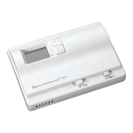
Page 3: Parts Diagram
Parts Diagram Battery Compartment Celsius/ Fahrenheit Jumper Electric/Gas Switch Heat Switch Fan Switch Room Temperature Setpoint ROOM Room Temperature LO BAT Low Battery Signal DIFF Temperature Differential Setting... -
Page 4: Specifications
Specifications Electrical rating: • Millivolt to 30 VAC/VDC • DC Power: 3.0 VDC (2 “AA” alkaline batteries included) • 1 amp maximum per terminal • 2 amp maximum total load Temperature control range: 45°F to 90°F (7°C to 32°C) Accuracy: ± 1°F (± 0.5°C) Differential Rage: 1°F to 3°F (0.5°C to 1.5°C) System configurations: 1-stage heat, gas, oil, electric Terminations: R, W, G... -
Page 5: General Description
General Description The SimpleComfort ® 1800 thermostat is a digital, mercury-free, non-programmable, electronic thermostat. • Compatible with single-stage heating systems • Compatible as a master thermostat in zoned system applications • Freeze Protection Feature: Protects pipes from freezing! If the room temperature drops to 40°F, the thermostat automatically turns on the heat;... -
Page 6: Replacing Wiring Labels
Replacing Wiring Labels Replace the old labels with the enclosed new labels. Type F, G Fan control relay H, W, 4 Heating control M, 4, RH, RS, R Transformer, hot side To Install Thermostat ELECTRICAL SHOCK HAZARD – Turn off power at the main service panel by removing the fuse or switching the appropriate circuit breaker to the OFF position before removing the existing thermostat. IMPORTANT: Thermostat installation must conform to local and national building and electrical codes and ordinances. -
Page 7: Installing And Changing Batteries
To Install Thermostat (continued) 10. Use supplied screws to mount thermostat base to wall. 11. Insert stripped, labeled wires in matching wire terminals. See “Wiring Diagrams” section of this manual (Pages 6-7). CAUTION!: Be sure exposed portion of wires does not touch other wires. 12. -
Page 8: Wiring Diagrams
Wiring Diagrams Heating Only 3-Wire, 2-Wire, Single Transformer Single Transformer or Millivolt... -
Page 9: Zone Valve/Damper Motor System
Zone Valve/Damper Motor System 3-Wire, Zone Valve/Damper Motor System 2-Wire, Zone Valve/Damper Motor System Note: Differential temperature may need to be increased for zone/damper systems (see Page 8). -
Page 10: Setting The Setpoint Temperature
Setting the Setpoint Temperature 1. Place Off/Heat switch in the Heat position. 2. Press the button a single time to see the current temperature setting. 3. Press the button until the desired temperature setpoint displays. 4. The new temperature setpoint is automatically saved in memory. After 5 seconds, the display returns to showing the current room temperature. -
Page 11: A Quick Test
A Quick Test Do not short jumper across terminals on the gas valve or at the system control to test installation. Action Set the Off/Heat switch to Heat; press the button until the set temperature is 3°F above the room temperature. - Page 12 ONE-YEAR LIMITED WARRANTY The Seller warrants its products against defects in material or workmanship for a period of one (1) year from the date of manufacture. The liability of the Seller is limited, at its option, to repair, replace or issue a non-case credit for the purchase prices of the goods which are provided to be defective.
Need help?
Do you have a question about the SC 1800 and is the answer not in the manual?
Questions and answers