
Related Manuals for Phoenix Contact FLM BK PB M12 DI 8 M12-EF


Summary of Contents for Phoenix Contact FLM BK PB M12 DI 8 M12-EF
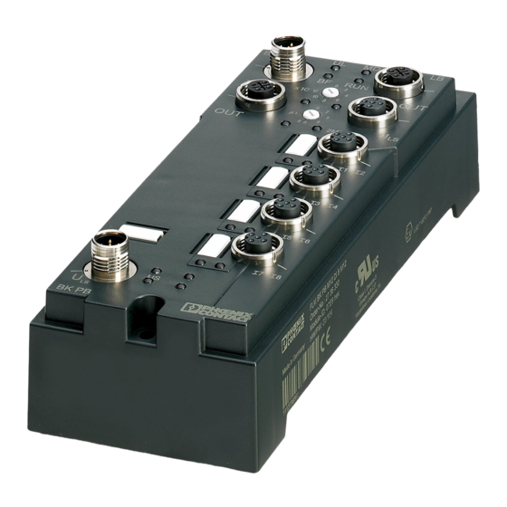
- Page 1 AUTOMATION User Manual UM EN FLM BK PB M12 DI 8 M12-EF Diagnostic and firmware functions of the FLM BK PB M12 DI 8 M12-EF bus coupler...
- Page 3 AUTOMATION User Manual Diagnostic and firmware functions of the FLM BK PB M12 DI 8 M12-EF bus coupler 2010-07-26 Designation: UM EN FLM BK PB M12 DI 8 M12-EF Revision: This user manual is valid for the FLM BK PB M12 DI 8 M12-EF bus coupler Order No.: 2773377...
- Page 4 Phoenix Contact accepts no liability for erroneous handling or damage to products from Phoenix Contact or third-party products resulting from disregard of information contained in this manual.
- Page 5 The receipt of technical documentation (in particular data sheets, installation instructions, manuals, etc.) does not constitute any further duty on the part of Phoenix Contact to furnish information on alterations to products and/or technical documentation. Any other agreement shall only apply if expressly confirmed in writing by Phoenix Contact.
- Page 6 Phoenix Contact. Violators are liable for damages. Phoenix Contact reserves all rights in the case of patent award or listing of a registered design. Third-party products are always named without reference to patent rights. The existence of such rights shall not be excluded.
-
Page 7: Table Of Contents
Table of Contents The Fieldline Modular Bus Coupler for PROFIBUS ..............1-1 Diagnostics ..........................2-1 Activating/deactivating the diagnostic formats............2-1 2.1.1 Diagnostics in the FLM BK PB M12 DI 8 M12-EF format ....2-2 2.1.2 Status PDU diagnostic format .............2-8 2.1.3 ID-specific diagnostic format ...............2-9 Local diagnostic indicators ................2-10... - Page 8 UM EN FLM BK PB M12 DI 8 M12-EF PHOENIX CONTACT 8097_en_00...
-
Page 9: The Fieldline Modular Bus Coupler For Profibus
– LED diagnostic and status indicators for bus operation and voltage supply – Short-circuit and overload protection of the sensor supply – Channel-specific diagnostics for different I/O devices – IP65/IP67 protection – IO-Link-Call (firmware 2.0 or later) 8097_en_00 PHOENIX CONTACT... - Page 10 UM EN FLM BK PB M12 DI 8 M12-EF For additional information about the bus coupler, please refer to the following documents: Data sheet: DB EN FLM BK PB M12 DI 8 M12-EF Handbücher: FLS FLM SYS INST UM E und FLS FLM PB SYS PRO UM E They can be downloaded at www.phoenixcontact.net/catalog.
-
Page 11: Diagnostics
You can select either: – FLM BK PB M12 DI 8 M12-EF Format – Status-PDU Diagnostics – ID-Specific Diagnostics By default, "FLM BK PB M12 DI 8 M12-EF Format" is activated. Figure 2-1 Diagnostic formats dialog box 8097_en_00 PHOENIX CONTACT... -
Page 12: Diagnostics In The Flm Bk Pb M12 Di 8 M12-Ef Format
UM EN FLM BK PB M12 DI 8 M12-EF 2.1.1 Diagnostics in the FLM BK PB M12 DI 8 M12-EF format This diagnostic format consists of the following blocks: PROFIBUS standard diagnostics ID-specific diagnostics Status diagnostics (terminal status) Channel-specific diagnostics... - Page 13 Diagnostics Table 2-1 FLM BK PB M12 DI 8 M12-EF format diagnostics Byte Bit 7 Bit 6 Bit 5 Bit 4 Bit 3 Bit 2 Bit 1 Bit 0 Meaning Block 3 Number of local bus devices Status PDU (header)
- Page 14 UM EN FLM BK PB M12 DI 8 M12-EF Table 2-1 FLM BK PB M12 DI 8 M12-EF format diagnostics Byte Bit 7 Bit 6 Bit 5 Bit 4 Bit 3 Bit 2 Bit 1 Bit 0 Meaning Block 5...
- Page 15 Slave has more diagnostic information than displayed in the telegram. Table 2-5 Byte: Master address 0-125 (00 Master address following parameterization, default address is 255 (FF Table 2-6 Byte 5 and 6: ID number 0-225 (00 ID number high byte 0-225 (00 ID number low byte 8097_en_00 PHOENIX CONTACT...
- Page 16 UM EN FLM BK PB M12 DI 8 M12-EF Block 2: ID-specific diagnostics The table 2-1 shows the faulty local bus devices. For every faulty terminal, a "1" is entered. In the first byte of the block, bits 0 to 5 specify the number of local bus devices and therefore the length L of the block (8 devices for each byte, maximum).
- Page 17 ET: 6 = Cable break ET: 7 = Upper limit value exceeded ET: 8 = Lower limit value exceeded ET: 9 = General error Block 5: Revision diagnostics Indicates the firmware version, e.g., C3 = Version 3 8097_en_00 PHOENIX CONTACT...
-
Page 18: Status Pdu Diagnostic Format
UM EN FLM BK PB M12 DI 8 M12-EF Block 6: Status PDU The sixth block is also encoded as a status PDU block, but in manufacturer-specific format. The information stored here does not usually need to be evaluated. Byte 5 indicates the baud rate at which the local bus is operated. -
Page 19: Id-Specific Diagnostic Format
PROFIBUS master address Manufacturer ID high byte (0C Manufacturer ID low byte (39 Block 2 Number of devices (values 0 to 16) Terminals 1 to 8 (values 0 to 255) Terminals 9 to 16 (values 0 to 255) 8097_en_00 PHOENIX CONTACT... -
Page 20: Local Diagnostic Indicators
UM EN FLM BK PB M12 DI 8 M12-EF Local diagnostic indicators The LEDs on the bus coupler show the Error type. B U S R U N R U N O U T 1 0 x 2 M B D... - Page 21 PCP error on a local bus device 1 Hz OFF: Voltage not present Green/red LED: Voltage supply for inputs IN1 to IN8 Green ON: Voltage supply present. Red ON: Overload or voltage supply too low. OFF: Voltage supply not present 2-11 8097_en_00 PHOENIX CONTACT...
- Page 22 UM EN FLM BK PB M12 DI 8 M12-EF 2-12 PHOENIX CONTACT 8097_en_00...
-
Page 23: Acyclic Communication (Dp/V1 And Pcp)
DP/V1 is a mechanism which corresponds to PCP and PROFIBUS. The FLM BK PB M12 DI 8 M12-EF bus coupler prepares the data records, which are sent via DP/V1 from the C1 or C2 master, for the PCP mechanism in the local bus. PCP data from the local bus in turn are realized by the bus coupler in DP/V1 telegrams.. -
Page 24: Pcp Communication Basics
UM EN FLM BK PB M12 DI 8 M12-EF PCP Communication Basics PCP (Peripherals Communication Protocol) controls the transmission of parameter data in the local bus. Special PCP services are available for this purpose. Application Example To explain the basics of PCP communication, the following concrete PCP application is... - Page 25 Program invocation – Program invocation type objects, i.e., program sequences that can be run. For additional information on PCP communication, please refer to the IBS SYS PCP G4 UM E user manual, Order No. 2745169. 8097_en_00 PHOENIX CONTACT...
-
Page 26: Acyclic Communication In Dp/V1 Mode
PCP access – 2 to 16 During the access onto the FLM BK PB M12 DI 8 M12-EF bus coupler use the well established DP/V1 format. Read and write accesses can be executed in one step (request -> response). The PCP data from I/O devices is usually addressed via 16-bit object indices. DP/V1 only has fields for 8-bit indices. - Page 27 Structure of the data depending on the service Access Service Data Write objects DP/V1 Write Request Object data (FLM BK PB M12 DI 8 M12-EF DP/V1 Write Response None Read objects DP/V1 Read Request None (FLM BK PB M12 DI 8 M12-EF...
- Page 28 UM EN FLM BK PB M12 DI 8 M12-EF – <Slot>: The slot of the device to be addressed in the station. The bus coupler is addressed with slot =0, the integrated DI 8 is addressed with slot =1 and starting with the first connected device with slot 2 up to 63.
- Page 29 I/O devices can be read and written. The station structure is as follows: – FLM BK PB M12 DI 8 M12-EF – FLM DIO 4/4 M12-2A – FLM AI 4 SF M12 –...
- Page 30 UM EN FLM BK PB M12 DI 8 M12-EF Example 1: Reading the connected local PCP devices and their status (Slot 0, Index 5 on the bus coupler) Read request (master -> slave) Data Data Structure 5E 00 05 20 DP/V1 Read / Slot / Index / Maximum Length Read request (slave ->...
- Page 31 FLM AI 4 SF as described above.The settings on channel 1 and 3 are identical as well as of channel 2 and 4. Bytes 9 and 12 are reserved and are indicated as 0. The Invoke ID had been mirrored and the status indicates that the communication was error-free. 8097_en_00 PHOENIX CONTACT...
- Page 32 UM EN FLM BK PB M12 DI 8 M12-EF 4. Example: Writing the object "Config Table" for channel 3 on the connected FLM AI 4 SF (Slot 3, Index 0080, Subindex 3) Write request (master -> slave) Data Data Structure...
- Page 33 2 bytes are also part of the PCP error data, however, they are not used in this example. If it does not equal zero, the respective data I/O device data sheet contains more detailed information. 3-11 8097_en_00 PHOENIX CONTACT...
- Page 34 UM EN FLM BK PB M12 DI 8 M12-EF 6. Example: In the Event of an Error: Reading an object on a device without PCP (Slot 2, Index 0080) Write request (master -> slave) Data Data Structure 5F 02 2F 05 06 00 00 80 00...
-
Page 35: Acyclic Communication In Dp/V0 Mode Via Process Data
The VC1 device (listed as "PD PCP x words" in the GDS file) can be configured at any position behind the FLM BK PB M12 DI 8 M12-EF bus coupler. We recommend to configure the VC1 device at the last position. In this way, the configured slot and the actual slot occupied by the I/O device will always be identical. - Page 36 UM EN FLM BK PB M12 DI 8 M12-EF Start Fragment: Byte 1: Service Byte 2: Device no. Byte 3 Invoke ID Byte 4: Index high Byte 5: Index low Byte 6: Subindex Byte 7: Length, if required Byte 8:...
- Page 37 Byte 1 - Service in end fragment: Byte 1 Request/ Reserved response Bit 7: Request/Response 0 = Request 1 = Response Bits 6 to 5: Fragment type 10 = Last fragment (end fragment) Bits 4 to 0: Reserved 3-15 8097_en_00 PHOENIX CONTACT...
- Page 38 UM EN FLM BK PB M12 DI 8 M12-EF Abort/Error Fragment: Byte 1: Service Byte 2: Error code, if required Byte n: Error code, if required Table 3-9 Byte 1 - Service in abort/error fragment: Byte 1 Request/ Reserved response...
- Page 39 For VC1, the parameters have the following meaning: - <Device no.> The FLM BK PB M12 DI 8 M12-EF bus coupler counts the device as 0, the integrated DI 8 as 1 and starting with the first connected node as device = 2...16.
-
Page 40: Examples Of Vc1 Services
UM EN FLM BK PB M12 DI 8 M12-EF Examples of VC1 Services 3.5.2 1. Example: Reading the connected local PCP devices and their status (slot 0, index 5 on the bus coupler) Read request (master -> slave) Data (8 Words VC1) - Page 41 00 00 00 00 00 00 00 00 00 00 00 00 Clear response The response indicates that the command has been received. Here, the status is positive (= 0) Via Clear, the communication data can be reset to the initial state. 3-19 8097_en_00 PHOENIX CONTACT...
- Page 42 UM EN FLM BK PB M12 DI 8 M12-EF 3. Example: Reading the object "Config Table" on the connected FLM AI 4 SF (slot 3, index 0080) Read request (master -> slave) - start fragment Data (4 Words VC1) Data Structure...
- Page 43 00 I 00 00 00 00 00 00 00 Clear Request / 7 bytes unused Clear Response (slave -> master) Data (4 Words VC1) Data Structure 00 00 00 00 00 00 00 00 Clear Response 3-21 8097_en_00 PHOENIX CONTACT...
- Page 44 UM EN FLM BK PB M12 DI 8 M12-EF 4. Example: Writing the object "Config Table" for channel 3 on the connected FLM AI 4 SF (slot 3, index 0080, subindex 3) Write request (master -> slave) - start fragment...
- Page 45 PCP error data, however, they are not used in this example. If it does not equal zero, the respective data I/O device data sheet contains more detailed information. Via Clear, the communication data can be reset to the initial state. 3-23 8097_en_00 PHOENIX CONTACT...
- Page 46 UM EN FLM BK PB M12 DI 8 M12-EF 6. Example: In the event of an error: reading an object on a device without PCP (Slot 2, Index 0080) Read request (master -> slave) Data (4 Words VC1) Data Structure...
-
Page 47: Dynamic Configuration
Configuration table in the STEP 7® hardware configurator The configuration, e.g., in STEP 7®, is carried out in the same way as for other modular slaves. The configuration can be created from the hardware catalog using drag & drop, see Figure 4-1. 8097_en_00 PHOENIX CONTACT... - Page 48 UM EN FLM BK PB M12 DI 8 M12-EF Open the "Properties" dialog box by double-clicking on a device. Figure 4-2 DI 8 features dialog The "Parameter Assignment" tab can be used to specify whether a device should be active or inactive, see Figure 4-3.
-
Page 49: Principle Of The Dynamic Configuration
(reservation of empty spaces) is also indicated here. Structure: Length of 8 bytes Bytes Byte 1 Byte 2 Byte 8 3 to 7 57 58 59 60 61 63 x Bit = 0: Device and slot inactive Bit = 1: Device and slot active 8097_en_00 PHOENIX CONTACT... - Page 50 UM EN FLM BK PB M12 DI 8 M12-EF Index 7: Activation / deactivation of devices and slots and bus reset Access: Only via DP/V0, command 8 Function: Indicates which devices are active / inactive. Deactivation via the parameter telegram (reservation of empty spaces) is also indicated here. In addition, a bus reset takes place.
-
Page 51: Startup
This is the "PD PCP x Words” (x = 4, 6, ...16) module. You can specify it as first or as last module in the station and you can select the data width and address in accordance with the options in the CPU. The residual devices can be configured as usual. 8097_en_00 PHOENIX CONTACT... -
Page 52: Options For Specifying The Active Configuration
UM EN FLM BK PB M12 DI 8 M12-EF 4.3.2 Options for Specifying the Active Configuration In the following example, the 8-channel digital devices are not part of the station, i.e., these devices are part of the maximum configuration, but are to be deactivated at this station. -
Page 53: Specification Of The Active Configuration Via Dp/V0
Index 7. In the course of this, the new devices are integrated into data traffic. Please note that during reset the device output data are reset to their device-specific reset values. 8097_en_00 PHOENIX CONTACT... - Page 54 UM EN FLM BK PB M12 DI 8 M12-EF 4 Words VC1 Write request (master -> slave) - start fragment Data (4 Words VC1) Data Structure 14 00 00 00 06 00 08 F2 Write / Slot / Invoke ID / Index High / Index Low / Subindex / Length / 1 byte data Write response (slave ->...
- Page 55 Write response (slave -> master) Data (4 Words VC1) Data Structure 88 00 02 05 F2 I 00 00 00 Read Write Response / Status / Length / Number of accessible devices / device status / 3 bytes unused 8097_en_00 PHOENIX CONTACT...
-
Page 56: Specification Of The Active Configuration Via Dp/V1
UM EN FLM BK PB M12 DI 8 M12-EF 4.3.4 Specification of the Active Configuration via DP/V1 For DP/V1 you can access the activation status via Index 6. Index 7 is not supported here because it was optimized for the access via process data interface in particular. - Page 57 If you want to use the "PD PCP x words" process data interface module (VC1), you can configure it at any position. However, we recommend to use the last position because here the configured slot and the actual slot will always be identical. 4-11 8097_en_00 PHOENIX CONTACT...
- Page 58 UM EN FLM BK PB M12 DI 8 M12-EF 4-12 PHOENIX CONTACT 8097_en_00...
-
Page 59: Io-Link
IOLD objects are accessed with the IO-Link call being a standardized read and write access. It uses the mechanisms of PROFIBUS I & M functions (via DP/V1). For further information on IO-Link call communication can be found in the AH EN FLS PB M12 IOL 4 M12 application note. 8097_en_00 PHOENIX CONTACT... - Page 60 UM EN FLM BK PB M12 DI 8 M12-EF PHOENIX CONTACT 8097_en_00...
-
Page 61: A Appendix
A service parameter has been specified with a value that is not permitted. Cause For example, an incorrect length specification or subindex that is not permitted. Remedy Check the parameters in the object description and send the service again with the corrected values. 8097_en_00 PHOENIX CONTACT... - Page 62 UM EN FLM BK PB M12 DI 8 M12-EF Communication Error Messages Table A-4 / 06 (object access unsupported) Meaning The service used cannot be applied to this object. Cause For example, a program sequence can be started or stopped, but not read.
-
Page 63: A 2 Error Codes For Dp/V1 And Vc1 Communication
Wrong sequence of fragments Wrong data length during access PCP PDU size of 64 bytes (58 bytes user data) per communication exceeded (Internal) timeout while reading (Internal) error when transmitting a request (Internal) error when receiving a service 8097_en_00 PHOENIX CONTACT... -
Page 64: A 3 Format Of The Parameter Telegram
UM EN FLM BK PB M12 DI 8 M12-EF Format of the Parameter Telegram This section provides a detailed description of the format of the parameters for the bus coupler and the input and output devices. This may be useful when setting parameters using acyclic services or if there is no interface for the simple selection of parameters. - Page 65 An additional byte is automatically used if the total length of the function block is exceeded. This byte specified the actual length of the function block. The first byte (header byte for the function blocks) is set to FF 8097_en_00 PHOENIX CONTACT...
- Page 66 UM EN FLM BK PB M12 DI 8 M12-EF After that the function blocks are decoded: a) PCP Function Block Byte x+1 Bit 7 to bit 6 01: PCP function block Bit 5 to bit 0 PCP function block length...
-
Page 67: B Object Dictionaries
Set bit 2 if the diagnostics of all connected terminals are to be read in again. This is only useful if terminals are connected for which object 18 (diag state) is implemented. Usually this includes all devices that use PCP. Therefore check in the relevant data sheet whether the terminal supports PCP. 8097_en_00 PHOENIX CONTACT... - Page 68 UM EN FLM BK PB M12 DI 8 M12-EF Bit 3 can be used in the context of dynamic configuration. If a new activation status is specified via object 6 or 7, it is mandatory. If the connection to the PROFIBUS master is then interrupted and if the original parameterization is transmitted by the master during restart, the activation status is maintained.
- Page 69 More bytes can also be transmitted, however only up to 2 bytes, as the station can only manage a maximum of 16 terminals. 8097_en_00 PHOENIX CONTACT...
- Page 70 UM EN FLM BK PB M12 DI 8 M12-EF In the case of read access, the amount of data is based on the number of configured and available devices. If, for example, k = 16 devices are configured, you will receive the response m = 2+1 bytes.
- Page 71 Each PROFIBUS device is equipped with an electronic name plate for unique identification. This nameplate can be accessed, for example, during startup or for maintenance purposes. Depending on the selected I & M function, either only read or read/write access is possible. 8097_en_00 PHOENIX CONTACT...
- Page 72 UM EN FLM BK PB M12 DI 8 M12-EF The following I & M function are supported: Table B-1 I & M functions (basic data) I & M basic data Access Description Header Manufacturer specification Read PBBK DI/EF I & M block...
- Page 73 Please note, that when writing to I & M functions I & M1 to I & M4, the nonvolatile memory of the device is accessed. The memory is designed for a maximum of 100,000 write access operations. 8097_en_00 PHOENIX CONTACT...
-
Page 74: B 2 Slot 1
UM EN FLM BK PB M12 DI 8 M12-EF Slot 1 On slot 1, indices are implemented with regard to the integrated DI 8: Index 13: PD IN Function: Input data of the integrated DI8 Access: Read Length: 1 byte...
Need help?
Do you have a question about the FLM BK PB M12 DI 8 M12-EF and is the answer not in the manual?
Questions and answers