Advertisement
Quick Links
I/O mapping
Simple I/O communication via 2-wire cables
Application note
107967_en_01
1
Description
This application note describes an I/O communication solu-
tion for company-internal 2-wire cables, e.g., telephone
cable or master cable. The range covered is up to
20 kilometers.
Extension modules receive the I/O signals. The signals are
then transmitted to the SHDSL extender via an RS-485 front
module.
The white thumbwheel on the extension modules is used to
set the I/O MAP address. Programming knowledge is not re-
quired.
You need the following:
Description
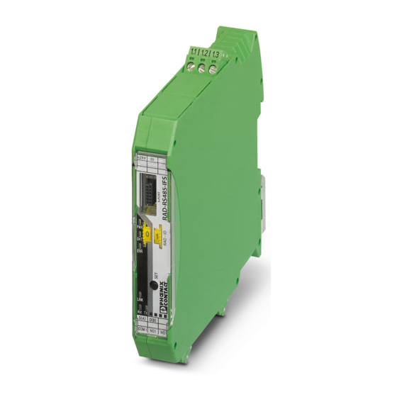
RS-485 front module
I/O extension module
SHDSL extender
Programming cable
Latest PSI-CONF software as of V2.50
Make sure you always use the latest documentation.
It can be downloaded using the links provided above.
© PHOENIX CONTACT 2018-06-06
Order No.
Designation
2702184
RAD-RS485-IFS
2901535
RAD-DI4-IFS
2901536
RAD-DOR4-IFS
2313669
PSI-MODEM-SHDSL/SERIAL
2903447
RAD-CABLE-USB
Link to product
phoenixcontact.net/product/2702184
phoenixcontact.net/product/2901535
phoenixcontact.net/product/2901536
phoenixcontact.net/product/2313669
phoenixcontact.net/product/2903447
Advertisement

Related Manuals for Phoenix Contact RAD-RS485-IFS


Summary of Contents for Phoenix Contact RAD-RS485-IFS
-
Page 1: Description
I/O mapping Simple I/O communication via 2-wire cables Application note 107967_en_01 © PHOENIX CONTACT 2018-06-06 Description This application note describes an I/O communication solu- tion for company-internal 2-wire cables, e.g., telephone cable or master cable. The range covered is up to 20 kilometers. -
Page 2: Table Of Contents
The DIN rail connector is used to bridge the power supply and communication. A separate power supply or data cable is therefore not required for the I/O extension module. • Install the SHDSL extender as described in the packing slip. 2 / 12 107967_en_01 PHOENIX CONTACT... -
Page 3: Schematic View
Schematic view Figure 2 Schematic view Setting the thumbwheel Table 1 RS-485 interface Use the thumbwheel on the front to address the wireless RAD-RS485-IFS PSI-MODEM-SHDSL/SERIAL modules and the extension modules. front module SHDSL extender Port 4.1 Port 3 Front module Port 4.2... -
Page 4: Configuring The Shdsl Extender
Connect the SHDSL extender to the PC using a USB cable. • Start the PSI-CONF software. • Select the SHDSL extender. Figure 3 Selecting the device • Click “Online Configuration” for device configuration. Figure 4 Online configuration 4 / 12 107967_en_01 PHOENIX CONTACT... - Page 5 SHDSL extender. • Select “Point-to-point wizard” to set up a point-to-point connection. Figure 5 Point-to-point wizard • In step 2, enter a name for the SHDSL extender. Figure 6 Assigning the device name 5 / 12 107967_en_01 PHOENIX CONTACT...
- Page 6 State of the cables – Insulation – Contact resistance – External errors There are two different modes to set the SHDSL rate: – Automatic – Manual • Select automatic mode. Figure 7 Configuring the SHDSL line 6 / 12 107967_en_01 PHOENIX CONTACT...
- Page 7 SHDSL extenders: – Interface type: RS-485 – Parity: Even – Baud rate (bps): 19200 – Stop bits: 1 – Data bits: 8 • Click “Accept settings for all devices”. Figure 8 Configuring the serial interface 7 / 12 107967_en_01 PHOENIX CONTACT...
- Page 8 I/O mapping • In step 5, the switching outputs can be configured. If external errors, for example, influence the transmission negatively, the switching output may trigger a warning. Figure 9 Configuring the switching outputs 8 / 12 107967_en_01 PHOENIX CONTACT...
- Page 9 Click “Transfer”. Wait until the transfer is complete. • Connect the USB cable to the second SHDSL extend- • Click “Transfer”. Figure 11 Transferring the settings to the SHDSL extender Configuration of the two SHDSL extenders is now complete. 9 / 12 107967_en_01 PHOENIX CONTACT...
-
Page 10: Increasing Timeout For The Front Modules
Use the USB cable in safe areas only. • Connect the front module to the PC using the USB cable. • Start the PSI-CONF software. • Select the front module. Figure 12 Selecting the device 10 / 12 107967_en_01 PHOENIX CONTACT... - Page 11 Click “Read”. • An online mode message appears. Click “OK”. • Save the project to the PC. Figure 13 Creating a project • Click “Edit in Individual Settings”. Figure 14 Editing the individual settings 11 / 12 107967_en_01 PHOENIX CONTACT...
- Page 12 Connect the USB cable to the second front module. • Repeat all the steps to increase the timeout for the sec- ond front module (from Page 10). PHOENIX CONTACT GmbH & Co. KG • Flachsmarktstraße 8 • 32825 Blomberg • Germany 12 / 12 107967_en_01 phoenixcontact.com...
Need help?
Do you have a question about the RAD-RS485-IFS and is the answer not in the manual?
Questions and answers