
Subscribe to Our Youtube Channel
Related Manuals for Pro'sKit MT-7028


Summary of Contents for Pro'sKit MT-7028
- Page 1 MT-7028 Network Toner & Probe Kit User’s Manual Edition, © 2017 Copyright by Prokit’s Industries Co., Ltd.
- Page 2 Thank your for your purchase of Pro’sKit MT-7028 Network Toner & Probe Kit. The Toner and Probe set is used to quickly trace and identify cables or wires within a group and also check the operation of telephone lines. With proper use and care, this instrument will provide many years of reliable service.
- Page 3 Dimension (L×W×D) 138× 80× 35 mm Weight 140g MT-7028 Receiver specifications Frequency 1kHz ≦90mA The Max. working current Compatible connectors RJ45(8 pin)/RJ11(6 pin) 4 Position mode switch (LED、NCV、OFF、 Function selection SCAN) Earphone jack Signal status indication 1 LED & Buzzer...
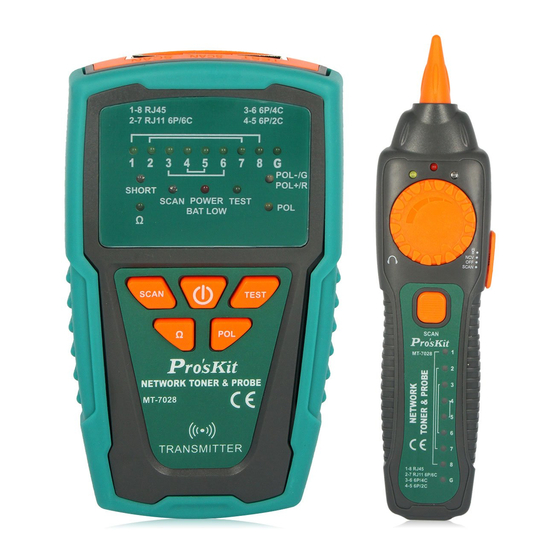
- Page 4 INTRODUCTION MT-7028 Transmitter: MT-7028 Transmitter Diagram 1.Test socket 2.RJ11(6 pin) Scan connectors 3.RJ45 Scan connectors 4.「1~8、G」 Cable map & Shielded indication 5.「SHORT」 Continuity test indication 6.「Ω」 Continuity function indicator 7.「SCAN」 Locating and Isolating cables function indicator 8. 「 POWER/BAT LOW」 Power ON/OFF & Battery low indicator 9. 「 TEST」...
-
Page 5: Operation
OPERATION 1. Locating and Isolating Cables: Using MT-7028 Networking Tone & Probe kit to locate and insolate cables using the 1KHz analog, also trace twisted wires (UTP,Cat 5, Cat 5e, Cat 6) and telephone line. Use with a patch cord for RJ45 / RJ11. Coaxial cable, general cable and various wiring boards can be tested by using with alligator clip cable. - Page 6 White noise from MT-7028 Receiver is normal when your Transmitter is near any of the interference. If you cannot locate the signal on 2-conductor cables, the cable may be shorted. Please keep away from the interference sources or turn off the electronic devices.
- Page 7 , the indicator of “POWER/ As the Figure 1 shown, when push BAT LOW” will light up and turn on the power. Push button for cable tracing. When the RED indicator flickers, the low-tone cable tracing is working. Push button again to feature the high-tone cable tracing, the RED indicator will flicker faster.
- Page 8 Repeat the steps of 6 and 7 to isolate the bundled cables. Caution • If you cannot locate the MT-7028 signal on 2-conductor cables, the cable may be shorted or opened. Use the Continuity Test (Fig. 2) to check for shorts or opens on coax and non-terminated cables.
- Page 9 Figure 3 Validating Cable Maps Different connectors generate different LED and sound indications as shown in Figure 4. • RJ45(8P/8C) LED indication:MT-7028 Transmitter (from 1-8 seconds in sequence) is synchronized with the MT-7028 Receiver cable map.
- Page 10 6P/4C each second from 3 to 6 in sequence, 6P/2C each second from 4 to 5 in sequence is synchronized with the MT-7028 Receiver cable map. If it encounters an empty line, the indication will cease. Figure 4 Different Connector’s Cable Map You can use the MT-7028 Transmitter and Receiver to validate the cable map on RJ11 and RJ45 connectors.
- Page 11 LED light will be off and the product will be standby for next operation. When the “1~8, G” LED indicator on MT-7028 transmitter lighted one by one, the cable (1~8, G) is good. If any of LED indicators is...
- Page 12 6.Coaxial Cable & Continuity Test: DANGER: Before testing, please be sure the power of receiver is OFF. To validate cable shield during cable map tests, do the following as: Connect the Transmitter to the circuit. Connect the test leads to the coaxial cable to be tested. Push “...
- Page 13 When doing the NCV testing, place the probe of MT-7028 receiver to the tested cable, the NCV indicator twinkles fast and the buzzer sounds, which means the tested object has AC 90~1000V. If there is no response of indicator and no buzzer sounds, it means the tested object has AC power less than 90V or there is no AC power on it.
- Page 14 MT-7028 音頻網路測試器 使用說明書 感謝您購買和使用 Pro’sKit MT-7028 音頻網路測試器,使用本儀器前請仔細閱 讀說明書,閱讀後請妥善保存,以備日後查閱。 特點概述: MT-7028音頻網路測試器--能定位、分離、導通、查找RJ45網路線(UTP、Cat 5、 Cat 5 e、Cat 6)、RJ11/12電話線,且能使用戶確認並診斷電纜,佈線的通路、 短路、斷路、交叉…等現象,並確認接線順序線號(線對表(Cable Map)和電話線 的接線極性。提供視覺和音頻信號強度指示,使測試距離與精確度更容易精準 掌握、測試一般電線接觸不良所產生的阻抗過大(>300Ω)的問題。MT-7028音頻 網路測試器--提供完整的配件,讓用戶可以輕易的檢測RJ45插座、RJ45連接線、 RJ11插座、RJ11連接線,並具有鱷魚夾,可應用於測試同軸電纜線、一般電線 和電信/網路接線板。 適用於電信、網路、數據通信、有線電視、室內/外配線⋯等專業的裝配、查線、 維修工程人員使用。 產品規格: MT-7028 音頻產生器 規格 音頻發射頻率 1kHz 音頻最大測試距離 ≧3 公里 線序/故障最大測試距離 300 米 最大工作電流 ≦65mA 音色 高/低 雙音調...
- Page 15 約 1 小時 電池低壓指示 6.5V (電源指示燈閃爍) 電池 DC 9.0V (NEDA 1604/ 6F22 DC9V ×1pcs) 外觀尺寸 (長× 寬×高) 138× 80× 35 mm 重量 140 公克 MT-7028 接收器 規格 音頻接收頻率 1kHz 最大工作電流 ≦90mA 可測試連接阜 RJ45(8 pin)/RJ11(6 pin) 共用插座 4 段滑動開關(非接觸驗電、關機、LED 照明、尋 功能選擇...
- Page 16 • 在更換電池以前,請關機!並斷開所有測試導線的連接。 • 僅使用9V電池,正確安裝在機殼內以提供電源。 • 如果不遵照指定方式使用本設備,則可能影響本產品提供的保護。 1. MT-7028 部件名稱 MT-7028 音頻產生器 外觀圖 1.RJ45(8 pin)/RJ11(6/4/2 pin)對線測試插座 2.RJ11(6 pin)Scan插座 3.RJ45Scan插座 4.「1~8、G」測試結果指示燈 5.「SHORT」短路測試結果指示燈 6.「Ω」短路/導通功能指示燈 7.「SCAN」尋線功能指示燈 8.「POWER/BAT LOW」電源指示燈 9.「TEST」線序/故障功能指示燈 10.「POL-/G,POL+/R」電話極性測試結果指示燈 11.「POL」電話極性功能指示燈 」尋線功能鍵 12.「 」短路/導通功能鍵 13.「 」電源開/關鍵 14.「...
- Page 17 」線序/故障功能鍵 15.「 」電話極性功能鍵 16.「 17.電池蓋。 MT-7028 接收器 外觀圖 1.音頻信號探頭 2.LED工作照明燈 3.電源指示燈 4.非接觸驗電(NCV)指示燈 5.信號強弱指示燈 6.音量旋扭 7.ø 3.5mm耳機座 8.4段功能開關 9.喇叭 」尋線功能鍵 10.「 11.「1~8、G」測試結果指示燈 12.RJ45(8 pin)/RJ11(6/4/2 pin)測試插座 13.電池蓋。...
- Page 18 (UTP、 Cat 5、Cat 5e、Cat 6)、電話線(Cat 3),搭配跳接線可以測試RJ45/RJ11 插座的接線,搭配鱷魚夾連接線,可測試同軸電纜線、一般電線和各種接線板。 警告 • 使用MT-7028音訊網路測試器不可以使用在帶電的線路上,操作前 應確實關閉所有電源。 • RJ45音訊尋線時,請使用RJ45 SCAN插座。RJ11(6P/6C/4C/2C) 音訊尋線時,請使用RJ11 SCAN插座。使用RJ11(6 pin)插座,搭配 鱷魚夾連接線,可測試同軸電纜線、一般電線和各種接線板。 注意 • 使用MT-7028音訊網路測試器的1KHz查找線路時,應儘量遠離或關 閉干擾源。如.具有變壓器、電感、線圈、馬達的電器設備⋯等;如果 接近干擾源,而MT-7028接收器產生接收的雜訊聲音,屬於正常狀 態;但如果影響操作判斷時,應予遠離或關閉干擾源。 • MT-7028音訊網路測試器的1KHz音訊信號,通過電路機板或分岔線 路或整捆電線(絞線)時,會有相互感應傳遞和信號強度的衰減的現 象。且無法穿透金屬配線管。 • 在搜索MT-7028音訊產生器的信號時,無需將MT-7028接收器的探 頭觸及線纜或接線板。 • 在使用MT-7028音訊網路測試器前,應確實檢查MT-7028音訊發射 器的黑色鱷魚夾,確實接地妥善。 • 在使用MT-7028音訊網路測試器耳機進行查線時,請將探頭遠離耳 機線,避免產生共鳴影響查線效果。 MT-7028音訊產生器所產生1KHz的音訊信號,具有雙音調高/低兩種音色可以選 擇,並可以配合所有連接介面和配件,提供這兩種高/低音訊信號。 查找電線 當你需要查找電線佈線位置或查找電線斷路位置時,請依照下列步驟(如圖一) 進行: 如(圖一)所示,先將MT-7028音訊產生器 的黑色鱷魚夾確實接 地,再將紅色鱷魚夾與待測線路的連接線或插座或接線板連接妥...
- Page 19 善。 如(圖一)所示,按下「 」電源開/關鍵,「POWER/BAT LOW」 紅色電源指示燈亮起,打開電源。再按下「 」尋線功能鍵後, 當「SCAN」尋線功能紅色指示燈閃爍時,表示低音調尋線測試的 功能啟動。再按一下此功能鍵後,當「SCAN」尋線功能紅色指示 燈快速閃爍時,表示高音調尋線測試的功能啟動。再按一下此功 能鍵, 「SCAN」 尋線功能紅色指示燈熄滅後,表示回到待機狀態。 如(圖一)所示,將接收器4段功能開關撥到SCAN或LED檔,按下接 收器中間的「 」尋線功能鍵時,紅色指示燈亮起,表示尋線測 試的功能啟動。當放開 「 」 尋線功能鍵時,紅色指示燈熄滅後, 表示,表示尋線測試的功能關閉。未插上耳機前喇叭有聲音輸出, 插上耳機後則喇叭無聲音輸出,聲音由耳機輸出。 使用MT-7028接收器 將音量旋鈕轉到最大,沿著塑膠配線管、走 線架、接線板或牆壁,查找佈線線路的大致位置。接近時,接收 器的喇叭響起音訊信號聲音,喇叭聲音越大,表示信號越強;同 時信號強弱指示燈LED亮紅色,指示燈明暗程度會隨信號強度改 變,當此指示燈越亮,表示信號越強。 旋轉音量旋鈕,控制音量由大到小,則可以改變查找電線的靈敏 度,將搜尋位置由30cm縮小到10cm以內,精確查找到電線。 (圖一) 查找電線 分離電線 當你需要尋找捆綁在一起的電纜其中一條電線,或多芯電纜中的其中一條芯線 時,請依照前面查找電線的步驟(1.)到(4.)進行(如圖一),然後再依照下列步驟(如 圖二)繼續進行: 將電纜撥開約30~45cm長,採用二分法,將電纜的芯線概略分為左...
- Page 20 右各一半,使用MT-7028接收器尋找目標芯線的位置,喇叭聲音較 大和LED燈比較亮(信號較強)的一邊,代表其中包含了你所要尋找的 目標芯線。 旋轉音量旋鈕,控制音量由大到小,則可以改變查找電線的靈敏度, 將搜尋位置由30cm縮小到10cm以內,精確找到目標芯線的位置。 重複前面二分法的(1)、(2)步驟,則可輕易找到目標芯線。 注意 如果不能正確分辨兩導線電纜上的音訊信號,可能電纜已短路或斷路。請使用 連通測試,檢查接電纜是否短路或斷路。 (圖二) 分離電線 3.線對表(Cable Map)測試: 可以使用MT-7028音訊產生器”TEST”兩用插座,配合MT-7028接收器 RJ45/RJ11兩用插座,測試RJ45網路線和RJ11電話線的線對表(Cable Map)。 搭配跳接線可以測試RJ45/RJ11插座的線對表(Cable Map) 。 線對表(Cable Map) 的功能可查找各種電纜布線上常見的:通路、短路、斷路、交叉的情況。 注意! 進行RJ45或RJ11線對表(Cable Map)測試時,RJ45網路線/RJ11電話線只能插 入音訊產生器的”TEST”兩用插座,不可使用RJ45 SCAN或RJ11 SCAN插座。 將待測線插入音訊產生器RJ45/RJ11 TEST插座 , 另一段插入接收器 插座。 按下「 」電源開/關鍵,「POWER/BAT LOW」紅色電源指示燈 亮起,打開電源。再按下MT-7028音訊產生器的「 」線序/故障...
- Page 21 功能鍵後,當「TEST」線序/故障功能綠色指示燈慢速閃爍時,表示 慢速線序/故障測試的功能啟動,線對表(Cable Map)的綠色LED開始 慢速掃描顯示。再按一下「 」線序/故障功能鍵後,當「TEST」 線序/故障功能綠色指示燈快速閃爍時,表示快速線序/故障測試的功 能啟動,線對表(Cable Map)的綠色LED開始快速掃描顯示。再按一 下此功能鍵後,當「TEST」線序/故障功能綠色指示燈熄滅後,表示 回到待機狀態。 (圖三) 線對表(Cable Map)測試 注意 • 線對表(Cable Map)測試時,LED慢速掃描顯示間隔約1秒鐘,LED 快速掃描顯示間隔約0.5秒鐘,每次由1~8、G順序掃描顯示。如果 遇到2條空線時,會有間歇2秒的現象,依此類推。 • 線對表(Cable Map)測試前,如有必要,可依前面所述方式,使用” 查找電線”的方法,先進行查找另一端正確的連接器或連接線。 MT-7028音訊產生器和MT-7028接收器上的LED輸出,不同線材的 線對表(Cable Map)顯示方式如下: • RJ45(8P/8C)的LED燈號顯示:MT-7028音訊產生器的線對表(Cable Map)LED,每1秒由1~8、G的順序,逐步顯示;並依接線順序,對 應MT-7028接收器上的線對表(Cable Map)LED同步顯示。(如圖四) • RJ11(6P/6C、6P/4C、6P/2C)的LED燈號顯示:MT-7028音訊產生 器的線對表(Cable Map)LED,6P/6C每1秒由2~7的順序;6P/4C每1...
- Page 22 秒由3~6的順序;6P/2C每1秒由4~5的順序),逐步顯示;並依接線 順序,對應MT-7028接收器上的線對表(Cable Map)LED同步顯示。 如果遇到空線時,會有顯示間歇的現象。(如圖四) (圖四) 不同線材的線對表(Cable Map) MT-7028音訊產生器和MT-7028接收器上的線對表(Cable Map)LED輸 出,通路、短路、斷路、交叉表示的方式如下: • 「通路」的LED燈號顯示:MT-7028音訊產生器的LED,第1~8、 G 個LED亮燈,對應MT-7028接收器上的LED,第1~8、G個LED同步 顯示。(如圖五) • 「短路」的LED燈號顯示:MT-7028音訊產生器的LED,第3個和第 4個LED依序亮燈,對應MT-7028接收器上的LED,第3個和第4個 LED同時點亮,但亮度較暗。(如圖五) (若同時短路跳線超過3根, 因電流供電不足,對應接收器上的LED亮度會更暗或不亮) • 「斷路」的LED燈號顯示:MT-7028音訊產生器的LED,第3個LED 不亮,對應MT-7028接收器上的LED,第3個LED不亮。(如圖五) • 「交叉」的LED燈號顯示:MT-7028音訊產生器的LED,第3個LED 亮燈,對應MT-7028接收器上的LED,第4個LED同步顯示;MT-7028 音訊產生器的LED,第4個LED亮燈,對應MT-7028接收器上的 LED,第3個LED同步顯示。(如圖五) 依照MT-7028音訊產生器和MT-7028接收器上的線對表(Cable Map)LED輸出,反復測試;並以LED顯示的線對表(Cable Map)確 認接線順序的正確性。...
- Page 23 (圖五)通路、短路、斷路、交叉 4.工作中的網路檢測: 注意: 此測試方法只能測試網線路通斷,不能檢測交叉或短路。 將MT-7028音訊產生器妥善連接RJ45(8P/8C)網路線或插座 、 另一端 連接在正在工作的網路交換機上。 按下「 」電源開/關鍵,「POWER/BAT LOW」紅色電源指示燈 亮起,打開電源。再按下MT-7028音訊產生器的「 」線序/故障 功能鍵後,當「TEST」線序/故障功能綠色指示燈慢速閃爍時,表 示慢速線序/故障測試的功能啟動,線對表(Cable Map)的綠色LED 開始慢速掃描顯示。再按一下 「 」 線序/故障功能鍵後,當 「TEST」 線序/故障功能綠色指示燈快速閃爍時,表示快速線序/故障測試的功 能啟動,線對表(Cable Map)的綠色LED開始快速掃描顯示。再按一 下此功能鍵後,當「TEST」線序/故障功能綠色指示燈熄滅後,表 示回到待機狀態。 當MT-7028音訊產生器上的「1~8、G」測試結果指示燈,按先後順 序逐一點亮時,表示網路線1~8、G全部連通,如有燈號未亮,代表...
- Page 24 線路故障。 5.同軸電纜線和電線連通測試: 警告: 測試前,應先確認並關閉電源。 當你需要確認同軸電纜線或電線連通是否有接觸不良時,請依照下列步驟進行: 先將MT-7028音訊產生器的黑色鱷魚夾,確實與待測電纜的一端接 頭、金屬部分連接妥善,再將紅色鱷魚夾,與待測電纜的另一端接頭、 金屬部分連接妥善。 按下「 」電源開/關鍵,「POWER/BAT LOW」紅色電源指示燈亮 起,打開電源。再按下MT-7028音訊產生器的「 」短路/導通功能鍵 後,當「Ω」短路/導通功能綠色指示燈亮起時,表示短路/導通測試的 功能啟動。再按一下此功能鍵後,當「Ω」短路/導通功能綠色指示燈 熄滅後,表示回到待機狀態。 當「SHORT」短路測試結果紅色指示燈亮起時,表示連通(阻抗 <300Ω)。當指示燈不亮時,表示無連通,或是遮蔽不良和連通不良(阻 抗>300Ω)。 6.電話正負極性測試: 當你需要確認電話線路的正負極性時,請依照下列步驟進行: 先將MT-7028音訊產生器的紅、黑色鱷魚夾,分別與待測電話線路的 連接線或插座或接線板的兩端連接妥善。 按下「 」電源開/關鍵,「POWER/BAT LOW」紅色電源指示燈亮 起,打開電源。再按下MT-7028音訊產生器的「 」電話極性功能鍵 後,當「POL」電話極性功能指示燈亮起時,表示電話正/負極性測試 的功能啟動。再按一下此功能鍵後,當「POL」電話極性功能指示燈 熄滅後,表示回到待機狀態。 「POL-/G,POL+/R」電話極性測試結果指示燈,是一個紅/綠雙色 LED指示燈: • 紅色指示燈亮起時,代表紅色鱷魚夾端為電話局線的”十”極,黑色 鱷魚夾端為電話局線的”一”極。 • 綠色指示燈亮起時,代表紅色鱷魚夾端為電話局線的”一”極,黑色 鱷魚夾端為電話局線的”十”極。 •...
-
Page 25: Ncv 非接觸驗電
7.NCV 非接觸驗電: 注意: 此項測試功能可以被廣泛應用在定位、分離、導通、查找、線對表(Cable Map)測試前,確認被測線路中是否有交流電壓,除可確保人身安全.避免 觸電外,也可以保護MT-7028音訊網路測試器,不被交流電壓損壞! 將4段功能選擇開關,撥切至「NCV」檔位後,電源指示燈亮起,表 示「NCV」非接觸驗電測試的功能啟動。 將MT-7028接收器的探頭靠近被測物,進行非接觸驗電(NCV)測試, 當非接觸驗電(NCV)指示燈快速閃爍、同時蜂鳴警報時,代表被測物 具有90~1000V交流電壓。當指示燈不亮、無蜂鳴警報時,代表被測 物的交流電壓低於90V或是沒有交流電壓。 8.維護與簡易故障排除: 維護: 警告 為避免可能發生的電擊或人體傷害,維護前,應關機並斷開所有測試導線 的連接。 小心 為避免損壞機殼,不要使用溶劑或磨蝕性去污粉。 用柔性軟布沾水後擰乾、或柔性軟布沾柔性皂液後擰乾,輕輕的擦拭機殼。 簡易故障排除: 故障 排除 電池電力不足:檢查音頻產生器和接收器的電池,如電壓 低於 6.5V,需更換電池。 接收器檔位不正確:請撥至 SCAN 檔或 LED 照明檔,其 接收器無法探測音頻 它檔位不能探測 SCAN 信號。 產生器的信號 帶遮罩的 STP 網線。 儀器故障:返回經銷商維修。... - Page 26 活 電 下 測 試 電 話 局 可能是電話局線信號頻率,與本音頻產生器的信號衝突, 線,接收器無法探測 請關閉電話交換機。 音頻產生器的信號 LED 指示燈損壞:返回經銷商維修 線 序 / 故 障 測 試 結 果 網路線或電話線接觸不良:請將網路線或電話線,重新插 顯示不正確 入 RJ45/RJ11 共用插座。 將開關撥到 SCAN 檔,按 SCAN 鍵,如 SCAN 指示燈閃 NCV 無法測試 亮明顯,則表明電池有電,如微弱閃亮或不亮,則電池電 量低,需更換電池 其它功能異常 儀器故障:返回經銷商維修...
- Page 27 MT-7028 音频网络测试器 使用说明书 感谢您购买和使用 Pro’sKit MT-7028 音频网络测试器,使用本仪器前请仔细阅 读说明书,阅读后请妥善保存,以备日后查阅。 特点概述: MT-7028音频网络测试器--能定位、 分离、 导通、 查找RJ45网络线(UTP、 Cat 5、 Cat 5 e、Cat 6)、RJ11/12电话线,且能使用户确认并诊断电缆,布线的通路、 短路、断路、交叉…等现象,并确认接线顺序线号(线对表(Cable Map)和电话线 的接线极性。还提供视觉和音频信号强度指示,使测试距离与精确度更容易精 准掌握和测试一般电线接触不良所产生的阻抗过大(>300Ω)的问题。 MT-7028音 频网络测试器--提供了完整的配件,让用户可以轻易的检测RJ45插座、RJ45连 接线、RJ11插座、RJ11连接线,并具有鳄鱼夹,可应用于测试同轴电缆线、一 般电线和电信/网络接线板。 适用于电信、网络、数据通信、有线电视、室内外配线⋯等专业的装配、查线、 维修工程人员使用。 产品规格: MT-7028 音频产生器 规格 音频发射频率 1kHz 音频最大测试距离 ≧3 公里 线序/故障最大测试距离 300 米...
- Page 28 约 1 小时 电池低压指示 6.5V (电源指示灯闪烁) 电池 DC 9.0V (NEDA 1604/ 6F22 DC9V ×1pcs) 外观尺寸 (长× 宽×高) 138× 80× 35 mm 重量 140 公克 MT-7028 接收器 规格 音频接收频率 1kHz 最大工作电流 ≦90mA 可测试连接阜 RJ45(8 pin)/RJ11(6 pin) 共享插座 4 段滑动开关(非接触验电、关机、LED 照明、寻 功能选择...
- Page 29 • 在更换电池以前,请关机!并断开所有测试导线的连接。 • 仅使用9V电池,正确安装在机壳内以提供电源。 • 如果不遵照指定方式使用本设备,则可能影响本产品提供的保护。 1.MT-7028 部件名称 MT-7028 音频产生器 外观图 1.RJ45(8 pin)/RJ11(6/4/2 pin)对线测试插座 2.RJ11(6 pin)Scan插座 3.RJ45Scan插座 4.「1~8、G」测试结果指示灯 5.「SHORT」短路测试结果指示灯 6.「Ω」短路/导通功能指示灯 7.「SCAN」寻线功能指示灯 8.「POWER/BAT LOW」电源指示灯 9.「TEST」线序/故障功能指示灯 10.「POL-/G,POL+/R」电话极性测试结果指示灯 11.「POL」电话极性功能指示灯 」寻线功能键 12.「 」短路/导通功能键 13.「 」电源开/关键 14.「 」线序/故障功能键 15.「...
- Page 30 」电话极性功能键 16.「 17.电池盖。 MT-7028 接收器 外观图 1.音频信号探头 2.LED工作照明灯 3.电源指示灯 4.非接触验电(NCV)指示灯 5.信号强弱指示灯 6.音量旋扭 7.ø 3.5mm耳机座 8.4段功能开关 9.喇叭 」寻线功能键 10.「 11.「1~8、G」测试结果指示灯 12.RJ45(8 pin)/RJ11(6/4/2 pin)测试插座 13.电池盖。...
- Page 31 Cat 5、Cat 5e、Cat 6)、电话线(Cat 3),搭配跳接线可以测试 RJ45/RJ11插座的接线,搭配鳄鱼夹连接线,可测试同轴电缆线、一般电线和 各种接线板。 警告 • 使用MT-7028音频网络测试器不可以使用在带电的线路上,操作前 应确认关闭所有电源。 • RJ45音频寻线时,请使用RJ45 SCAN插座。RJ11(6P/6C/4C/2C) 音频寻线时,请使用RJ11 SCAN插座。使用RJ11(6 pin)插座,搭配 鳄鱼夹连接线,可测试同轴电缆线、一般电线和各种接线板。 注意 • 使用MT-7028音频网络测试器的1KHz查找线路时,应尽量远离或关 闭干扰源。如.具有变压器、电感、线圈、马达的电器设备⋯等;如果 接近干扰源,而MT-7028接收器产生接收的噪声声音,属于正常状 态;但如果影响操作判断时,应予远离或关闭干扰源。 • MT-7028音频网络测试器的1KHz音频信号,通过电路机板或分岔线 路或整捆电线(绞线)时,会有相互感应传递和信号强度的衰减的现 象。且无法穿透金属配线管。 • 在搜索MT-7028音频产生器的信号时,无需将MT-7028接收器的探 头触及线缆或接线板。 • 在使用MT-7028音频网络测试器前,请先将MT-7028音频发射器的 黑色鳄鱼夹进行接地作业。 • 在使用MT-7028音频网络测试器耳机进行查线时,请将探头远离耳 机线,避免产生共鸣影响查线效果。 MT-7028音频产生器所产生1KHz的音频信号, 具有双音调高/低两种音色可以选 择,并可以配合所有连接接口和配件,提供这两种高/低音频信号。 查找电线 当你需要查找电线布线位置或查找电线断路位置时,请依照下列步骤(如图一)
- Page 32 进行: 如(图一)所示,先将MT-7028音频产生器 的黑色鳄鱼夹妥善接地,再将 红色鳄鱼夹与待测线路的连接线或插座或接线板连接妥善。 如(图一)所示,按下「 」电源开/关键,「POWER/BAT LOW」红色 电源指示灯亮起, 打开电源。 再按下 「 」 寻线功能键后, 当 「SCAN」 寻线功能红色指示灯闪烁时, 表示低音调寻线测试的功能启动。再单击 此功能键后,当「SCAN」寻线功能红色指示灯快速闪烁时,表示高音 调寻线测试的功能启动。再单击此功能键,「SCAN」寻线功能红色指 示灯熄灭后,表示回到待机状态。 如(图一)所示,将接收器4段功能开关拨到SCAN或LED檔,按下接收器 中间的「 」寻线功能键时,红色指示灯亮起,表示寻线测试的功能 启动。当放开「 」寻线功能键时,红色指示灯熄灭后,表示,表示 寻线测试的功能关闭。 未插上耳机前喇叭有声音输出, 插上耳机后则喇 叭无声音输出,声音由耳机输出。 使用MT-7028接收器 将音量旋钮转到最大,沿着塑料配线管、走线架、 接线板或墙壁,查找布线线路的大致位置。接近时,接收器的喇叭响起 音频信号声音, 喇叭声音越大, 表示信号越强; 同时信号强弱指示灯LED 亮红色,指示灯明暗程度会随信号强度改变,当此指示灯越亮,表示信 号越强。 旋转音量旋钮,控制音量由大到小,则可以改变查找电线的灵敏度,将 搜寻位置由30cm缩小到10cm以内,精确查找到电线。...
- Page 33 图二)继续进行: 将电缆拨开约30~45cm长,采用二分法,将电缆的芯线概略分为左右各 一半,使用MT-7028接收器寻找目标芯线的位置,喇叭声音较大和LED 灯比较亮(信号较强)的一边,代表其中包含了你所要寻找的目标芯线。 旋转音量旋钮,控制音量由大到小,则可以改变查找电线的灵敏度,将 搜寻位置由30cm缩小到10cm以内,精确找到目标芯线的位置。 重复前面二分法的(1.)、(2.)步骤,则可轻易找到目标芯线。 注意 如果不能正确分辨两导线电缆上的音频信号,可能电缆已短路或断路。请使用 连通测试,检查接电缆是否短路或断路。 (图二) 分离电线 : 3.线对表(Cable Map)测试 可以使用MT-7028音频产生器”TEST”两用插座,配合MT-7028接收器 RJ45/RJ11两用插座,测试RJ45网络线和RJ11电话线的线对表(Cable Map)。 搭配跳接线可以测试RJ45/RJ11插座的线对表(Cable Map)。 线对表(Cable Map) 的功能可查找各种电缆布在线常见的:通路、短路、断路、交叉的情况。 注意! 进行RJ45或RJ11线对表(Cable Map)测试时,RJ45网络线/RJ11电话线只能插 入音频产生器的”TEST”两用插座,不可使用RJ45 SCAN或RJ11 SCAN插座。 将待测线插入音频产生器RJ45/RJ11 TEST插座,另一段插入接收器插 座。 按下「 」电源开/关键,「POWER/BAT LOW」红色电源指示灯亮...
- Page 34 起,打开电源。再按下MT-7028音频产生器的「 」线序/故障功能键 后,当「TEST」线序/故障功能绿色指示灯慢速闪烁时,表示慢速线序/ 故障测试的功能启动,线对表(Cable Map)的绿色LED开始慢速扫描显 示。再单击「 」线序/故障功能键后,当「TEST」线序/故障功能绿 色指示灯快速闪烁时,表示快速线序/故障测试的功能启动,线对表 (Cable Map)的绿色LED开始快速扫描显示。再单击此功能键后,当 「TEST」线序/故障功能绿色指示灯熄灭后,表示回到待机状态。 (图三) 线对表(Cable Map)测试 注意 • 线对表(Cable Map)测试时,LED慢速扫描显示间隔约1秒钟,LED 快速扫描显示间隔约0.5秒钟,每次由1~8、G顺序扫描显示。如果 遇到2条空线时,会有间歇2秒的现象,依此类推。 • 线对表(Cable Map)测试前,如有必要,可依前面所述方式,使用” 查找电线”的方法,先进行查找另一端正确的连接器或连接线。 MT-7028音频产生器和MT-7028接收器上的LED输出,不同线材的线对 表(Cable Map)显示方式如下: • RJ45(8P/8C)的LED灯号显示:MT-7028音频产生器的线对表 (Cable Map)LED,每1秒由1~8、G的顺序,逐步显示;并依接线顺 序, 对应MT-7028接收器上的线对表(Cable Map)LED同步显示。 (如 图四) • RJ11(6P/6C、6P/4C、6P/2C)的LED灯号显示:MT-7028音频产生...
- Page 35 器的线对表(Cable Map)LED,6P/6C每1秒由2~7的顺序;6P/4C每 1秒由3~6的顺序;6P/2C每1秒由4~5的顺序),逐步显示;并依接线 顺序,对应MT-7028接收器上的线对表(Cable Map)LED同步显示。 如果遇到空线时,会有显示间歇的现象。(如图四) (图四) 不同线材的线对表(Cable Map) MT-7028音频产生器和MT-7028接收器上的线对表(Cable Map)LED输 出,通路、短路、断路、交叉表示的方式如下: • 「通路」的LED灯号显示:MT-7028音频产生器的LED,第1~8、 G个 LED亮灯, 对应MT-7028接收器上的LED, 第1~8、 G个LED同步显示。 (如 图五) • 「短路」的LED灯号显示:MT-7028音频产生器的LED,第3个和第4个 LED依序亮灯,对应MT-7028接收器上的LED,第3个和第4个LED同时 点亮,但亮度较暗。(如图五) (若同时短路跳线超过3根,因电流供电不 足,对应接收器上的LED亮度会更暗或不亮) • 「断路」 的LED灯号显示: MT-7028音频产生器的LED, 第3个LED不亮, 对应MT-7028接收器上的LED,第3个LED不亮。(如图五) • 「交叉」 的LED灯号显示: MT-7028音频产生器的LED, 第3个LED亮灯, 对应MT-7028接收器上的LED,第4个LED同步显示;MT-7028音频产生 器的LED,第4个LED亮灯,对应MT-7028接收器上的LED,第3个LED 同步显示。(如图五)
- Page 36 (图五) 通路、短路、断路、交叉 4.工作中的网络检测: 注意:此测试方法只能测试网线路通断,不能检测交叉或短路。 将MT-7028音频产生器妥善连接RJ45(8P/8C)网络线或插座、另一端连 接在正在工作的网络交换机上。 按下「 」电源开/关键,「POWER/BAT LOW」红色电源指示灯亮 起,打开电源。再按下MT-7028音频产生器的「 」线序/故障功能键 后,当「TEST」线序/故障功能绿色指示灯慢速闪烁时,表示慢速线序/ 故障测试的功能启动,线对表(Cable Map)的绿色LED开始慢速扫描显 示。再单击「 」线序/故障功能键后,当「TEST」线序/故障功能绿 色指示灯快速闪烁时,表示快速线序/故障测试的功能启动,线对表 (Cable Map)的绿色LED开始快速扫描显示。再单击此功能键后,当 「TEST」线序/故障功能绿色指示灯熄灭后,表示回到待机状态。 当MT-7028音频产生器上的「1~8、G」测试结果指示灯,按先后顺序逐 一点亮时, 表示网络线1~8、 G全部连通, 如有灯号未亮, 代表线路故障。 5.同轴电缆线和电线连通测试: 警告:测试前,应先将电源关闭。 当你需要确认同轴电缆线或电线连通是否有接触不良时,请依照下列步...
- Page 37 骤进行: 先将MT-7028音频产生器的黑色鳄鱼夹,确认与待测电缆的一端接头、 金属部分连接妥善,再将红色鳄鱼夹,与待测电缆的另一端接头、金属 部分连接妥善。 按下「 」电源开/关键,「POWER/BAT LOW」红色电源指示灯亮 起,打开电源。再按下MT-7028音频产生器的「 」短路/导通功能键 后,当「Ω」短路/导通功能绿色指示灯亮起时,表示短路/导通测试的功 能启动。再单击此功能键后,当「Ω」短路/导通功能绿色指示灯熄灭后, 表示回到待机状态。 当 「SHORT」 短路测试结果红色指示灯亮起时, 表示连通(阻抗<300Ω)。 当指示灯不亮时,表示无连通,或是遮蔽不良和连通不良(阻抗>300Ω)。 6.电话正负极性测试: 当你需要确认电话线路的正负极性时,请依照下列步骤进行: 先将MT-7028音频产生器的红、黑色鳄鱼夹,分别与待测电话线路的连 接线或插座或接线板的两端连接妥善。 按下「 」电源开/关键,「POWER/BAT LOW」红色电源指示灯亮 起,打开电源。再按下MT-7028音频产生器的「 」电话极性功能键 后,当「POL」电话极性功能指示灯亮起时,表示电话正/负极性测试的 功能启动。再单击此功能键后,当「POL」电话极性功能指示灯熄灭后, 表示回到待机状态。 「POL-/G, POL+/R」 电话极性测试结果指示灯, 是一个红/绿双色LED 指示灯: • 红色指示灯亮起时,代表红色鳄鱼夹端为电话局线的”十”极,黑色鳄鱼 夹端为电话局线的”一”极。 • 绿色指示灯亮起时,代表红色鳄鱼夹端为电话局线的”一”极,黑色鳄鱼 夹端为电话局线的”十”极。...
- Page 38 将4段功能选择开关,拨切至「NCV」档位后,电源指示灯亮起,表示 「NCV」非接触验电测试的功能启动。 将MT-7028接收器的探头靠近被测物,进行非接触验电(NCV)测试,当 非接触验电(NCV)指示灯快速闪烁、同时蜂鸣警报时,代表被测物具有 90~1000V交流电压。当指示灯不亮、无蜂鸣警报时,代表被测物的交 流电压低于90V或是没有交流电压。 8.维护与简易故障排除: 维护: 警告 为避免可能发生的电击或人体伤害,维护前,应关机并断开所有测试导线的连 接。 小心 为避免损坏机壳,不要使用溶剂或磨蚀性去污粉。 用柔性软布沾水后拧干、或柔性软布沾柔性皂液后拧干,轻轻的擦拭机壳。 简易故障排除: 故障 排除 电池电力不足: 检查音频产生器和接收器的电池, 如电压 低于 6.5V,需更换电池。 接收器档位不正确:请拨至 SCAN 檔或 LED 照明檔,其 接收器无法探测音频 它檔位不能探测 SCAN 信号。 产生器的信号 带屏蔽的 STP 网线。 仪器故障:返回经销商维修。 活 电 下 测 试 电 话 局...
- Page 39 量低,需更换电池 中国地区产品保固卡 购买日期 店章 公司名称 联络电话 电子邮箱 联络地址 产品型号 □ MT-7028-C 在正常使用情况下,自原购买日起 12 个月免费维修保证(不含 ※ 耗材、消耗品) 。 产品保固卡需盖上店章、日期章,其保固效力始生效。 ※ 本卡请妥善保存,如需维修服务时,请出示本卡以为证明。 ※ 保固期满后,属调整、保养或是维修性质之服务,则酌收检修工 ※ 时费用。若有零件需更换,则零件费另计。 产品保固说明 保固期限内,如有下列情况者,维修中心则得酌收材料成本或修 理费(由本公司维修人员判定): • 对产品表面的损伤,包括外壳裂缝或刮痕 • 因误用、疏忽、不当安装或测试,未经授权打开产品修理,修 改产品或者任何其它超出预期使用范围的原因所造成的损害 • 因事故、火灾、电力变化、其它危害,或自然灾难所造成的损 害。 非服务保证内容: • 机件本体外之消耗品:如电池...等消耗品...
- Page 40 制造商:宝工实业股份有限公司 地 址:台湾新北市新店区民权路 130 巷 7 号 5 楼 电 话:886-2-22183233 E-mail: PK@mail.prokits.com.tw 生产商:上海宝工工具有限公司 地址:上海市浦东新区1365弄25号 原产地:中国 上海 销售公司:深圳畅联贸易有限公司 地址:深圳市福田区红荔西路上步工业区403栋东座5楼 电话:0755-83692415 传真:0755-83692143 400服务热线:400-1699-629 E-mail: shenzhen@mail.prokits.com.tw 寶 工 實 業 股 份 有 限 公 司 PROKIT’S INDUSTRIES CO., LTD http://www.prokits.com.tw Email: pk@mail.prokits.com.tw ©...
Need help?
Do you have a question about the MT-7028 and is the answer not in the manual?
Questions and answers