Advertisement
CTR 8 • Setup Guide
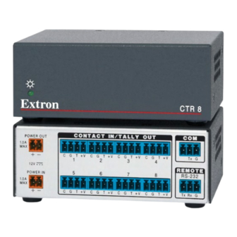
The Extron CTR 8 provides contact closure input switching for most Extron switchers with
RS-232 capability. It allows simple push-buttons to remotely switch and mute video sources.
NOTE:
www.extron.com.
Installation
1
Power LED
Lights green when
ATTENTION:
the unit is receiving
Verify that the CTR 8 is disconnected from the power source before proceeding.
power.
1
POWER OUT
1.0A
MAX
Figure 1.
CTR 8 Rear Panel
a
POWER IN
1.0A
MAX
POWER OUT
1.0A
MAX
b
Contact closure inputs with tally outputs — Connect contact closure source devices
POWER IN
to these 4-pole female captive screw connectors. Wire each connector as shown below.
1.0A
MAX
Contact (C)
Ground (G)
Tally output (T)
Tally voltage (+V)
NOTE:
•
For "Show Me" cables, the ground pin connection is optional.
•
Do not connect "Show Me" cables to the +V pin.
Transmit (Tx)
Receive (Rx)
1
Power LED — Lights green when the unit is receiving power.
For full installation and operation details, see the CTR 8 User Guide, available at
Turn the input and output devices off and unplug their power cords.
POWER OUT
1.0A
MAX
C
G
1
12V
5
POWER IN
1.0A
MAX
C
G
DC power input with loop-through — Wire the external 12 VDC power supply
as shown below and connect it to the Power In connector.
Ridges
Smooth
SECTION A–A
Power Supply Output Cord
The Power Out connector allows power to be looped to an Extron device that
uses +12 VDC voltage. Follow the same pin diagram above to connect a device to
the Power Out connector.
CONTACT IN / TALLY OUT
T +V
C
G
T +V
C
G
T +V
2
3
6
7
T +V
C
G
T +V
C
G
T +V
2
A
A
CTR 8
CTR 8
COM
C
G
T +V
Tx
G
4
REMOTE
8
RS-232
C
G
T +V
Tx Rx G
3
3/16"
(5 mm) Max.
4
Advertisement
Table of Contents

Subscribe to Our Youtube Channel
Related Manuals for Extron electronics CTR 8


Summary of Contents for Extron electronics CTR 8
- Page 1 Power LED — Lights green when the unit is receiving power. CTR 8 • Setup Guide The Extron CTR 8 provides contact closure input switching for most Extron switchers with RS-232 capability. It allows simple push-buttons to remotely switch and mute video sources.
- Page 2 Display 500mA INPUT COM 3 RELAY 1 2 3 4 Tx Rx S G S G 68-2524-50 Rev. A 12 13 © 2013 Extron Electronics — All rights reserved. All trademarks mentioned are the property of their respective owners. www.extron.com...
Need help?
Do you have a question about the CTR 8 and is the answer not in the manual?
Questions and answers