Table of Contents
Advertisement
Quick Links
Roger Access Control System
Installation guide for
PR602LCD type access controller
Firmware version: 1.18.6 or newer
Document version: Rev. J
© 2016 ROGER sp. z o.o. sp.k. All rights reserved. This document is subject to the Terms of Use in their current version published at
the
www.roger.pl
website of the Roger sp. z o.o. sp.k. company (hereinafter referred to as ROGER).
Advertisement
Table of Contents

Summary of Contents for Roger PR602LCD-DT-I
- Page 1 Firmware version: 1.18.6 or newer Document version: Rev. J © 2016 ROGER sp. z o.o. sp.k. All rights reserved. This document is subject to the Terms of Use in their current version published at www.roger.pl website of the Roger sp. z o.o. sp.k. company (hereinafter referred to as ROGER).
-
Page 2: Table Of Contents
PR602LCD Installation guide Rev.J.doc 2016-10-21 Contents 1. Introduction ........................3 1.1 This manual ........................3 2. Description and specification ..................3 3. Installation ........................4 3.1 Terminals/wires and connection diagram ................4 3.2 LED indicators ........................6 3.3 Power supply ........................6 3.4 Connection of door lock ...................... -
Page 3: Introduction
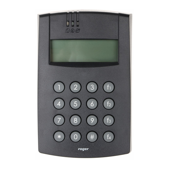
PR602LCD type controller is single door access controller used in RACS 4 access control system. Both versions of PR602LCD-DT i.e. PR602LCD-DT-I and PR602LCD-DT-O controllers are functionally identical, but differ in regard of working conditions. The first one is just sole controller installed indoors while the second one includes both the controller and ME-7 metal enclosure and can be installed outdoors. -
Page 4: Installation
Remaining PR602LCD: approx. 410g Certificates 3. I NSTALLATION 3.1 Terminals/wires and connection diagram PR602LCD-DT-I, PR602LCD-DT-O and PR602LCD-I controllers are equipped with screw terminals, while PR602LCD-O controller is equipped with connection cable. Table 3. PR602LCD controller type terminals/wires Wire colour Screw Description... - Page 5 PR602LCD Installation guide Rev.J.doc 2016-10-21 Gray-pink REL1-NC REL1 relay output (NC) Yellow TAMPER A Tamper switch Gray TAMPER B Tamper switch Fig. 1 PR602LCD type controller connection diagram 5/16...
-
Page 6: Led Indicators
PR602LCD Installation guide Rev.J.doc 2016-10-21 3.2 LED indicators Controllers are equipped with 3 LED indicators. Their functions and colours are specified in table 4 below. Functioning of LEDs can be verified by means of included MASTER card after connection of power supply to the controller. -
Page 7: Communication With Controller
CLK/DTA, Wiegand or Magstripe bus. RACS CLK/DTA is the addressable bidirectional communication standard developed by Roger company. Addresses of all devices connected to CLK and DTA lines must be properly configured in range of 0..15. Factory default address of peripheral devices can be changed according to procedures specified in their manuals but in majority of cases it is not necessary to modify the addresses at all. -
Page 8: Prt And Third Party Readers (Wiegand And Magstripe)
Wiegand/Magstripe reader does not work properly with the controller, it might be necessary to use PR-GP module. The PR-GP works as electrical interface between reader and controller. In order to determine if PR-GP might be useful, please contact Roger technical support. Fig. 4 Connection of Wiegand/Magstripe reader 3.7 Input and output lines... -
Page 9: Relay Outputs
PR602LCD Installation guide Rev.J.doc 2016-10-21 connection with GND is interrupted. Every input is internally connected (pulled up) to the power supply plus (+12V) through a 15kΩ resistor. 3.7.2 Relay outputs Controllers offer one relay output (REL1) with single switching contact. Maximum load for REL1 equals to 30V/1.5A. -
Page 10: Wall Mounting
PR602LCD Installation guide Rev.J.doc 2016-10-21 3.8 Wall mounting Fig. 5 Installation of PR602LCD type controller 10/16... - Page 11 PR602LCD Installation guide Rev.J.doc 2016-10-21 Fig. 6 Installation of PR602LCD-DT-O controller 11/16...
-
Page 12: Installation Guidelines
PR602LCD Installation guide Rev.J.doc 2016-10-21 3.9 Installation guidelines Install devices in such way as to ensure easy access to screw terminals and jumpers (RST, FDM) located inside the controller – see fig. 7. Prior to controller installation it is recommended to configure its address (ID number) – see 4.1 Controller address. -
Page 13: Addressing During Memory Reset Procedure
4.1.4 Addressing by means of command entered with keypad All commands for manual programming of controller by means of keypad are specified in the document Functional description of PRxx2 series controllers, which is available at www.roger.pl. Following Keypad Command can be used for addressing:... -
Page 14: Controller Programming
4.4 Firmware update The latest versions of firmware and Roger ISP software are available at www.roger.pl. In order to update firmware it is necessary to connect the device by means of RS485 bus to communication interface (UT-2USB or RUD-1) and then connect the interface to PC with installed Roger ISP software. -
Page 15: Ordering Information
Once more reset device (place and remove jumper on RST pins or switch power off/on) In Firmware window select firmware *.hex file (can be downloaded from www.roger.pl) and then select the button Program After firmware upload remove jumper from FDM pins and reset device (place and remove... - Page 16 Weight of the equipment is specified in the document. Contact: Roger sp. z o.o. sp.k. 82-400 Sztum Gościszewo 59 Tel.: +48 55 272 0132 Fax: +48 55 272 0133 Tech.


Need help?
Do you have a question about the PR602LCD-DT-I and is the answer not in the manual?
Questions and answers