Table of Contents
Advertisement
Quick Links
Roger Access Control System
Installation guide for
PR102DR/PR102DR-BRD Access Controllers
Firmware version: 1.18.6 or newer
Hardware version: 1.0
Document version: Rev. E
© 2016 ROGER sp. z o.o. sp.k. All rights reserved. This document is subject to the Terms of Use in their current version published at
the
www.roger.pl
website of the Roger sp. z o.o. sp.k. company (hereinafter referred to as ROGER).
Advertisement
Table of Contents

Related Manuals for Roger PR102DR


Summary of Contents for Roger PR102DR
- Page 1 Hardware version: 1.0 Document version: Rev. E © 2016 ROGER sp. z o.o. sp.k. All rights reserved. This document is subject to the Terms of Use in their current version published at www.roger.pl website of the Roger sp. z o.o. sp.k. company (hereinafter referred to as ROGER).
-
Page 2: Table Of Contents
2. Description and Specification ..................3 3. Installation ........................4 3.1 Terminals and connection diagram ..................4 3.2 Front panel ........................6 3.2.1 PR102DR controller ....................... 6 3.2.2 PR102DR-BRD controller ....................6 3.3 Power supply ........................7 3.4 Connection of door lock ...................... 7 3.5 Communication with controller .................... -
Page 3: Introduction
PR102DR is single door access controller used in RACS 4 access control system. Both PR102DR and PR102DR-BRD versions are functionally identical but differ mechanically. PR102DR is installed inside plastic enclosure fitted to mounting on DIN 35 mm rail, while PR102DR-BRD is just a PCB module without enclosure. -
Page 4: Installation
PR102DR Installation Guide Rev.E.doc 2017-09-18 3. I NSTALLATION 3.1 Terminals and connection diagram Fig. 1 PR102DR and PR102DR-BRD controllers Table 2. PR102DR terminals Terminal Description Terminal Description RACS CLK/DTA comm. bus IN1 input line RACS CLK/DTA comm. bus Ground RS485 communication bus... - Page 5 PR102DR Installation Guide Rev.E.doc 2017-09-18 Fig. 2 PR102DR connection diagram 5/13...
-
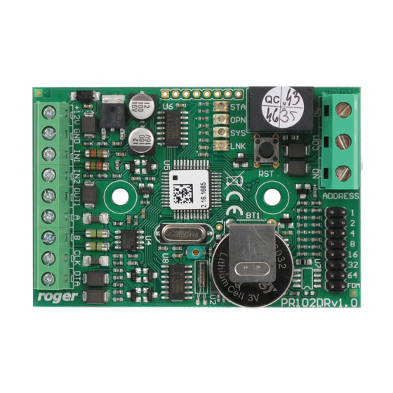
Page 6: Front Panel
3.2.2 PR102DR-BRD controller According to fig. 4, PR102DR-BRD is equipped with 4 LED indicators and RST button on its PCB. The button can be used to restart the controller in the same way as in case of powering device off and then on. -
Page 7: Power Supply
PR102DR Installation Guide Rev.E.doc 2017-09-18 Table 5. LED indicators of PR102DR-BRD controller Armed/Disarmed mode Door unlocked Various signalling functions Data transmission by means of RS485 bus 3.3 Power supply Controllers require 12VDC nominal power supply. The power should be connected to the 12V line and GND line. -
Page 8: Communication Of Controller With Peripheral Devices
RACS CLK/DTA bus can be connected to the controller in distance up to 500m, but such conditions are not guaranteed by the manufacturer. PR102DR controller can operate with two PRT series readers, XM-2 I/O expander, up to four XM-8 expanders dedicated to access control in elevators and HRT82FK function key panel. Addresses of PRT readers must be ID=0 and ID=1, the address of XM-2 expander must be ID=5, addresses of XM-8 expanders must be in range of ID=8..11 and the address of HRT82FK must be ID=12. -
Page 9: Configuration
Following addressing methods are available: By means of jumpers During update of controller firmware by means of Roger ISP software (so called Fixed ID) Manually during Memory Reset procedure By means of PR Master software The first two methods enable configuration of hardware addresses while the remaining two enable configuration of software addresses. -
Page 10: Addressing During Firmware Update (Fixed Id)
PR102DR Installation Guide Rev.E.doc 2017-09-18 Fig. 6 Addressing jumpers 4.1.2 Addressing during firmware update (Fixed ID) FixedID can be set during update of the controller firmware by means of RogerISP software. Prior to firmware upload, RogerISP software offers the possibility to set Fixed ID address in range of 00..99 or disable it (FixedID=None). -
Page 11: Simplified Memory Reset Procedure (Firmware 1.18.6 Or Newer)
PR102DR Installation Guide Rev.E.doc 2017-09-18 4.2.1 Simplified Memory Reset Procedure (firmware 1.18.6 or newer) Simplified Memory Reset restores default settings with controller address ID=00. Remove connections to CLK and IN1 terminals Connect CLK with IN1 Restart the controller (press RESET button or switch power supply off/on) - LED OPEN... -
Page 12: Firmware Update
4.4 Firmware update The latest versions of firmware and Roger ISP software are available at www.roger.pl. In order to update firmware it is necessary to connect the device by means of RS485 bus to communication interface (UT-2USB or RUD-1) and then connect the interface to PC with installed Roger ISP software. -
Page 13: Product History
PR102DR Installation Guide Rev.E.doc 2017-09-18 6. P RODUCT HISTORY Table 7. Product history Product version Released Description PR102DR v.1.0 08/2012 The first commercial version of the product This symbol placed on a product or packaging indicates that the product should not be disposed of with other wastes as this may have a negative impact on the environment and health.
Need help?
Do you have a question about the PR102DR and is the answer not in the manual?
Questions and answers