Roger PR622 Installation Manual
Hide thumbs Also See for PR622:

Advertisement

Quick Links

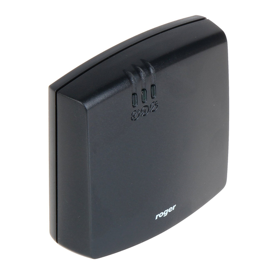
Roger Access Control System
Installation guide for PR612, PR622, PR312EM,
PR312EM-BK, PR312MF and PR312MF-BK access
controllers
Firmware version: 1.18.6 or newer
Document version: Rev. H
© 2016 ROGER sp. z o.o. sp.k. All rights reserved. This document is subject to the Terms of Use in their current version published at
the
www.roger.pl
website of the Roger sp. z o.o. sp.k. company (hereinafter referred to as ROGER).

Advertisement

Table of Contents
loading
Need help?

Need help?

Do you have a question about the PR622 and is the answer not in the manual?

Questions and answers

Summary of Contents for Roger PR622

  • Page 1 Firmware version: 1.18.6 or newer Document version: Rev. H © 2016 ROGER sp. z o.o. sp.k. All rights reserved. This document is subject to the Terms of Use in their current version published at www.roger.pl website of the Roger sp. z o.o. sp.k. company (hereinafter referred to as ROGER).
  • Page 2: Table Of Contents

    PR612 PR622 PR312EM PR312MF Installation guide 2020-10-07 Contents 1. Introduction ........................3 2. Description and specification ..................3 3. Installation ........................4 3.1 Terminals/wires and connection diagram ................4 3.2 LED indicators ........................5 3.3 Power supply ........................6 3.4 Connection of door lock ...................... 6 3.5 Communication with controller ....................
  • Page 3: Introduction

    PR612, PR622, PR312EM, PR312EM-BK, PR312MF and PR312MF-BK are single door access controllers used in RACS 4 access control system. All devices are functionally identical but PR612, PR312EM and PR312MF are equipped with keypad while PR622, PR312EM-BK and PR312MF-BK are ®...
  • Page 4: Installation

    PR612 PR622 PR312EM PR312MF Installation guide 2020-10-07 PR622: 85 x 85 x 27 mm PR312EM/PR312MF: 152,5 x 46 x 23(35)mm PR312EM-BK/PR312MF-BK: 152,5 x 46 x 23(35)mm Weight PR612/PR622: approx. 120g PR312EM/PR312EM-BK: approx. 150g PR312MF/PR312MF-BK: approx. 150g Certificates 3. I NSTALLATION 3.1 Terminals/wires and connection diagram...
  • Page 5: Led Indicators

    PR612 PR622 PR312EM PR312MF Installation guide 2020-10-07 Fig. 1 Connection diagram 3.2 LED indicators Controllers are equipped with 3 LED indicators. Their functions and colours are specified in table 3 below. Functioning of LEDs can be verified by means of included MASTER card after connection of power supply to the controller.
  • Page 6: Power Supply

    PR612 PR622 PR312EM PR312MF Installation guide 2020-10-07 Table 3. LED indicators Symbol Name Colour Description STATUS Red/Green Armed/Disarmed Mode respectively OPEN Green Door unlocking SYSTEM Orange Various system functions and programming 3.3 Power supply Controllers require 12VDC nominal power supply. The power should be connected to the +12V line and -12V line.
  • Page 7: Communication Of Controller With Peripheral Devices

    CLK/DTA. RACS CLK/DTA is the addressable bidirectional communication standard developed by Roger company. Addresses of all devices connected to CLK and DTA lines must be properly configured in range of 0..15. Factory default address of peripheral devices can be changed according to procedures specified in their manuals but in majority of cases it is not necessary to modify the addresses at all.
  • Page 8: Wall Mounting

    PR612 PR622 PR312EM PR312MF Installation guide 2020-10-07 3.8 Wall mounting Fig. 3 Installation of PR612 controller 8/16...
  • Page 9 PR612 PR622 PR312EM PR312MF Installation guide 2020-10-07 Fig. 4 Installation of PR622 controller 9/16...
  • Page 10 PR612 PR622 PR312EM PR312MF Installation guide 2020-10-07 Fig. 5 Installation of PR312EM/PR312MF controllers (standard enclosure base) 10/16...
  • Page 11 PR612 PR622 PR312EM PR312MF Installation guide 2020-10-07 Fig. 6 Installation of PR312EM/PR312MF controllers (additional enclosure base) 11/16...
  • Page 12: Installation Guidelines

    PR612 PR622 PR312EM PR312MF Installation guide 2020-10-07 3.9 Installation guidelines  Install devices in such way as to ensure easy access to screw terminals and jumpers (RST, FDM) located inside the controller – see fig. 7.  Prior to controller installation it is recommended to configure its address (ID number) – see 4.1 Controller address.
  • Page 13: Addressing During Firmware Update (Fixed Id)

    Functional description of PRxx2 series controllers, which is available at www.roger.pl. PR622 and PR312EM-BK controllers which are not equipped with keypad can also be programmed manually. In such case it is necessary to connect PRT series reader with keypad (e.g. PRT12LT) to such controller.
  • Page 14: Full Memory Reset Procedure (Controller With Keypad)

    4.4 Firmware update The latest versions of firmware and Roger ISP software are available at www.roger.pl. In order to update firmware it is necessary to connect the device by means of RS485 bus to communication interface (UT-2USB or RUD-1) and then connect the interface to PC with installed Roger ISP...
  • Page 15: Ordering Information

     Once more reset device (place and remove jumper on RST pins or switch power off/on)  In Firmware window select firmware *.hex file (can be downloaded from www.roger.pl) and then select the button Program  After firmware upload remove jumper from FDM pins and reset device (place and remove...
  • Page 16: Product History

    PR612 PR622 PR312EM PR312MF Installation guide 2020-10-07 CPR32-NET- Electronic module of network controller UT-4DR Ethernet-RS485 communication interface: UT-2USB USB-RS485 communication interface: RUD-1 Portable USB-RS485 communication interface with 12VDC/0.12A output XM-2DR I/O expander XM-8DR I/O expander (elevator access control) 6. P RODUCT HISTORY Table 5.

This manual is also suitable for:

Pr612Pr312emPr312em-bkPr312mfPr312mf-bkPr312

Table of Contents