Table of Contents
Advertisement
Quick Links
I 56- 3888- 105
DESCRIPTION
The LT FL01 Series is part of the Fire Alarm Aspiration Sensing
Technology
(FAAST) family. FAAST is an advanced fire detection
®
system for use where early warning and very early warning are a
requirement. The system continuously draws air from the controlled
environment through a series of sampling holes to monitor the
environment for smoke particulate.
The FL01 is the stand-alone version of the FAAST LT range and is
available in 3 different models:
FL0111E - Has single channel capability with one laser smoke
sensor.
FL0112E - Has single channel capability with two laser smoke
sensors in a common chamber for coincidence
detection.
FL0122E - Has two channel capability with two laser smoke
sensors in separate chambers. (One sensor for each
channel).
This guide provides information for mounting and basic installation
using the unit's default factory settings.
information please see the FAAST LT Advanced Setup and Control
Guide - reference D200-100-00.
SPECIFICATIONS
Electrical Characteristics
Voltage Range:
Supply Current:
1 Channel:
2 Channel:
Configurable Input: Activation Time:
Relay Contact Ratings:
Environmental Ratings
Temperature:
Relative Humidity:
IP Rating:
Mechanical
Exterior Dimensions:
Wiring:
Maximum Single Pipe Length:
Maximum Branched Pipe Length:
D200-101-00
FIRE ALARM ASPIRATION SENSING TECHNOLOGY
STAND-ALONE FAAST LT MODELS FL0111E FL0112E FL0122E
For more extensive
18.5 - 31.5 VDC
170mA (typical); 360mA (max) @
24 VDC 25
C (excluding sounders)
o
270mA (typical); 570mA (max) @
24 VDC 25
C (excluding sounders)
o
2s (min)
2.0 A @ 30 VDC, 0.5A @ 30 VAC
-10°C to 55°C
10% to 93% (non-condensing)
65
See Figure 1
0.5 mm² to 2 mm² max
100m (Classes B & C)
160m (2 x 80m, Class C)
QUICK INSTALLATION GUIDE
50 mm
60 mm
110 mm
356 mm
Figure 1: Dimensions and Knock-Outs
Maximum Number of Holes:
Pipe Spec (EN54-20 Compliance):
Outside Pipe Diameter:
Shipping Weight:
PARTS LIST
Description
FAAST LT unit
Mounting bracket
3-pin Terminal block
4-pin Terminal block
2-pin Terminal block
47 k-ohm EOL Resistor
USB Cable
Front Panel Labelling Pack
Wiring Diagram Label
Installation Kit CD
Quick Installation Guide
Aspirating Smoke Detectors supplied and installed within the
EU must conform to the EU Construction Products Regulation
(CPR) 305/2011 and the related European Product Standard EN
54-20. FAAST LT has been tested and certified to ensure that it
conforms to the necessary Standards, but strict adherence to this
instruction guide is advised to ensure that the installation meets
the requirements of the CPR.
The performance of this system is dependent upon the pipe
network. Any extension or modification to the designed
installation may cause improper operation. The operational
effects of such changes need to be verified using the PipeIQ
2 design software.
1
E N G L I S H
50 mm
See Table 1A
to EN 61386
(Crush 1, Impact 1, Temp 31)
25mm (nom) or 27mm (nom)
6.5kg (inc sensors)
Quantity
1
1
6
1
3
2
1
1
1
1
1
Important Note
Warning
®
44 mm
56 mm
135 mm
I56-3888-105
Advertisement
Table of Contents

Subscribe to Our Youtube Channel
Related Manuals for System Sensor FAAST LT FL01 Series


Summary of Contents for System Sensor FAAST LT FL01 Series
- Page 1 E N G L I S H FIRE ALARM ASPIRATION SENSING TECHNOLOGY ® QUICK INSTALLATION GUIDE I 56- 3888- 105 STAND-ALONE FAAST LT MODELS FL0111E FL0112E FL0122E 50 mm 50 mm 60 mm 44 mm 56 mm DESCRIPTION 110 mm The LT FL01 Series is part of the Fire Alarm Aspiration Sensing 135 mm 356 mm...
-
Page 2: Physical Installation
This equipment and all associated pipe work must be installed in accordance with all relevant codes and regulations. PHYSICAL INSTALLATION Figure 4: How to Knock Out Cable Front Panel Labels Gland Holes The LT FL01 is shipped without the front panel labels fixed in place. This allows the installer to choose the language required for the installation from the Front Panel Labelling Pack. - Page 3 Figure 7: Sequence (1 to 9) to Mount the Detector on the Bracket Pipe Hole Configuration Figure 8 below shows the pipe holes available on the unit. Each unit has 2 pipe holes per channel connected together like a T-Piece. 99 mm If using a 1 channel unit, holes 3 and 4 do not function.
-
Page 4: Wiring Installation
Exhaust Pipe Whenever the FAAST LT is installed outside the risk area, return of the exhaust air back into the protected area can reduce flow faults due to pressure difference. SAMPLING AREA SAMPLING AREA WIRING INSTALLATION Power, Alarm and Control Connections CHANNEL 1 FILTER CHANNEL 2 FILTER EARTH BAR... - Page 5 Fitting the Terminal Blocks WARNING: Switching Inductive Loads To insert the terminal blocks into the unit use the following method: FAAST LT 1 Insert a corner of the block into the slot (see a). 2 Push the length of the block into the slot until the block ‘clicks’ into place, the 2 upper hooks on the block should be visible (see c).
-
Page 6: External Reset
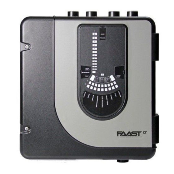
POWERING UP Using Default Settings 1. Connect a suitable 24VDC supply (complying with European ALARM Standard EN 54-4) to pins 1 and 2 on terminal block T1 (See Table 2) PREALARM 2. Check the voltage at the connector. Make sure it is within the required voltage range. - Page 7 Table 4: Front Panel Indicators and Fault Descriptions INDICATOR ACTION WARNING OR TROUBLE COMMENT / ACTION CHANNEL 1/2 ON Red Channel is in alarm (relay is set) No delay with default settings ALARM 1 BLINK Green when sensor is polled Not in alarm CHANNEL 1/2 PRE- ON Yellow...
- Page 8 PREALARM SMOKE LEVEL 2 Table 5: Front Panel Buttons INITIALIZATION BUTTON NORMAL Mode MAINTENANCE Mode POWER RESET FAULT When pressed for 2 s, starts PASSWORD When pressed for 2 s latched alarms, faults and PROCEDURE to enter Maintenance sounders (relays) are reset SMOKE LEVEL 2 mode.
-
Page 9: Laser Safety Information
Class A B & C The smoke sensors are located under the sensor cover (see Figure Aspirating Smoke Detectors 9 displayed earlier in the guide). To access the sensors, follow the System Sensor Europe sequence below: Pittway Tecnologica S.r.l. Via Caboto 19/3,...
Need help?
Do you have a question about the FAAST LT FL01 Series and is the answer not in the manual?
Questions and answers