
Related Manuals for PERCo TTR-07.1


Summary of Contents for PERCo TTR-07.1
- Page 1 Electromechanical Tripod Turnstile with Automatic Anti Panic Arms TTR-07.1 ASSEMBLY AND OPERATION MANUAL...
- Page 2 Electromechanical Tripod Turnstile with Automatic Anti-Panic Arms TTR-07.1 Assembly and Operation Manual...
-
Page 3: Table Of Contents
CONTENT APPLICATION......................3 OPERATION CONDITIONS..................3 TECHNICAL SPECIFICATIONS .................4 DELIVERY SET......................5 Standard delivery set ..................5 Optional equipment supplied on request:............5 BRIEF DESCRIPTION ....................7 Main features ......................7 Design.........................7 Control over the turnstile ..................9 Input and output signals and their parameters when operating the turnstile ..10 Control modes of the turnstile ................11 Operation with the RC panel ................12 Operation with the WRC ...................13... -
Page 4: Application
Manual carefully, and this quality product will provide many years of trouble-free use. Assembly and Operation Manual (hereinafter - the Manual) for the TTR-07.1 electromechanical tripod turnstile with automatic anti-panic folding arms (hereinafter - the turnstile) contains data that is necessary for the most full use of operating advantages of the turnstile as well as chapters on packaging, installation and maintenance. -
Page 5: Technical Specifications
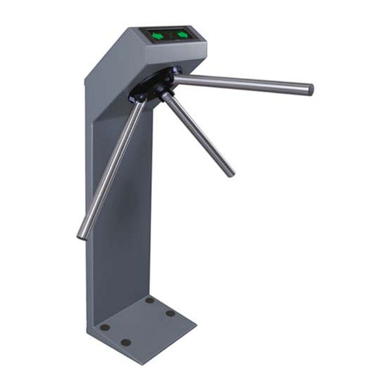
×1054 mm Turnstile net weight ................... max. 38 kg Figure 1. TTR-07.1 tripod turnstile. Overall dimensions MPS 8×0.12 mm. MAX allowed cable length – 40m. Using of cables more than 40 m long may result in interferences in a control line. -
Page 6: Delivery Set
TTR-07.1 Electromechanical Tripod Turnstile 4 DELIVERY SET 4.1 Standard delivery set Basic equipment: Turnstile housing ......................1 Hub with barrier arms and fastening ................. 1 RC panel with cable min. 6.6 m long ................1 Installation tools: Ø30 mm plug ........................5 Ø16 mm plug ........................ - Page 7 Assembly and Operation Manual Figure 2. Turnstile overall view 1 – turnstile housing; 2 – cover with LED indication display; 3 – hub; 4 – hub fastening bolts; 5 – barrier arm; 6 – AC power cable; 7 – turnstile power supply; 8 –...
-
Page 8: Brief Description
TTR-07.1 Electromechanical Tripod Turnstile 5 BRIEF DESCRIPTION 5.1 Main features The turnstile can be operated from the RC panel or WRC as well as from an ACS. The turnstile is supplied with safe voltage — maximum 14V. The turnstile has power consumption — maximum 72W (in start-up mode). - Page 9 Assembly and Operation Manual Figure 3. RC panel overall view 1, 2, 3 – buttons LEFT, RIGHT, STOP for setting the passage mode; 4, 5 – green indicators «Left», «Right»; 6 – red indicator «Stop», 7 – RC cable. There are three control buttons on the RC front panel intended for setting the turnstile operating modes.
-
Page 10: Control Over The Turnstile
TTR-07.1 Electromechanical Tripod Turnstile XT6 (AntiPanic) connector block to connect the electromagnet of automatic anti-panic unblocking device; J1 connector to select the turnstile control mode, the jumper is fixed — the pulse control mode, the jumper is not fixed — the potential control mode. The jumper is fixed at the factory before the delivery ... -
Page 11: Input And Output Signals And Their Parameters When Operating The Turnstile
Assembly and Operation Manual 5.3.5 The ACS controller outputs are connected to the contacts GND, Unlock A, Stop and Unlock B of the XT1.L. connector block. 5.3.6 The ACS controller inputs are connected to the contacts Common, PASS A, PASS B, Ready and Det Out of the XT1.H. connector block. 5.3.7 Pin assignments of the CLB connector blocks are given in Fig. -
Page 12: Control Modes Of The Turnstile
TTR-07.1 Electromechanical Tripod Turnstile Note: For generating of a high-level signal at all the input contacts (Unlock A, Stop, Unlock B, Fire Alarm and Detector) 2kOhm resistors connected to the power supply bus “+ 5V” are used. The control element* must provide the following signal characteristics: * the relay contact as the control element: minimum switched current ................max. -
Page 13: Operation With The Rc Panel
Assembly and Operation Manual 5.5.3 Control over the turnstile is effected by input of the control signal to the turnstile at both control modes. The passage waiting time in the pulse control mode is 5 seconds regardless of the control signal length. In the potential control mode the passage waiting time equals the length of the control signal. -
Page 14: Operation With The Wrc
TTR-07.1 Electromechanical Tripod Turnstile 5.6.2.3 The microcontroller traces the status of the optical arm rotation sensors, which become active/passive in a certain consequence at the barrier arm rotation, and counts the time passed since the moment of pushing the RC button corresponding to the permitted passage direction А... - Page 15 Assembly and Operation Manual If intrusion detector is not connected, you must install the jumper between pins DETECTOR and GND to the “XT1.L” connector block. On delivery, this jumper is installed. 5.9.3 If the turnstile is locked (the “Always locked” mode /“Both directions closed” mode when both directions are locked, Tables 2 and 3) and a signal comes from the intrusion detector, the “Alarm”...
-
Page 16: Emergency Unblocking Of The Turnstile
TTR-07.1 Electromechanical Tripod Turnstile 5.10 Emergency unblocking of the turnstile Emergency unblocking of the turnstile is automatically performed at a power supply loss, e.g. breakdown of connected power supply unit. At that the barrier arm automatically falls down ensuring free passage. The turnstile will remain in such condition until the power is restored. -
Page 17: Marking And Packaging
Assembly and Operation Manual 6 MARKING AND PACKAGING The turnstile has the marking on the turnstile housing in the form of a label located on the inner panel of the turnstile housing (to get access to the label unscrew the fixing bolt of the cover (2), located beneath the hub (3) and carefully lift up the cover with the LED indication display (2) by turning it in direction of the display). -
Page 18: Installation Instructions
TTR-07.1 Electromechanical Tripod Turnstile 8 INSTALLATION INSTRUCTIONS 8.1 Installation details Caution! Follow the safety requirements during the installation (see clause 7.1) Correct turnstile installation provides its functionality and lifetime. Please carefully study and follow the installation instructions. Caution! The manufacturer shall not be liable for any damage caused as the result of... -
Page 19: Installation Tools
Assembly and Operation Manual 8.2 Installation tools 1.2÷1.5 kW hammer drill; Ø16 mm hard-alloyed drill bits; Floor chaser for electric raceway; Flat slot screwdriver No.2; Cross-head screwdriver; Horn-type and socket wrenches: S17, S13 and S10; ... - Page 20 TTR-07.1 Electromechanical Tripod Turnstile Figure 10. Floor anchor position and cable entries for housing installation (turnstile housing is dotted) 5. Remove the cover with LED indication display (2) in the following way: unscrew the central bolt of the cover with LED indication display (2), located beneath the hub (3);...
- Page 21 Assembly and Operation Manual 8. Check serviceability and accuracy of all the electrical connections. 9. Fasten all the cables in two points to the hole in the turnstile housing horizontal plane, using hook and loop cable ties. 10. Connect the indication board cable header to the control mechanism connector and mount the cover with LED indication display (2) back into its place in the reverse order.
- Page 22 TTR-07.1 Electromechanical Tripod Turnstile Figure 11. Connection layout (description is given in Table 1)
-
Page 23: Operation Instructions
Assembly and Operation Manual 9 OPERATION INSTRUCTIONS It is prohibited: To operate the turnstile without following the operation safety requirements (see Clause 7.2). To move through the turnstile passage area any objects with dimensions exceeding the width of the passageway. ... - Page 24 TTR-07.1 Electromechanical Tripod Turnstile Table 2. Pulse control mode (the jumper is set on the J1 connector) The turnstile Actions Indication on Indication on № Turnstile status operating modes to do the RC panel the LED display The red Always locked...
-
Page 25: Operating Modes Of The Turnstile In Potential Control Mode
For urgent evacuation of people from business facilities in case of fire, natural calamities and other emergencies, the additional emergency exit should be provided. Such emergency exit can be the automatic anti-panic rotary section PERCo-BH02. The additional emergency exit can be provided by the turnstile passage area. Construction of the turnstile enables immediate clear of passage way without use of any special keys or tools. -
Page 26: Troubleshooting
TTR-07.1 Electromechanical Tripod Turnstile 9.5 Troubleshooting Possible faults, which can be cleared by the users themselves, are listed in Table 4. Table 4. Possible faults and remedy Fault Possible cause Remedy At the power-up the turnstile Switch off the turnstile power supply from the AC doesn’t work, and there is... -
Page 27: Maintenance
(1) base; tighten the anchor bolts (13); put the plastic plugs (14) into their places. In case of any defects revealed during v isual check please apply to the PERCo Technical Support Department (the PERCo TSD). -
Page 28: Transportation And Storage
TTR-07.1 Electromechanical Tripod Turnstile Figure 12. Location of the interior components of the turnstile housing (a, b, c – lubrication points) 1 – stop spring bracket; 2 – mechanism base; 3 –stop spring pulling pin; 4 –stop spring; 5 – resetting mechanism pusher lever; 6 – arm rotation sensor disk;... -
Page 29: Appendix А Control Signal Algorithm In Pulse Control Mode
Assembly and Operation Manual Control signal algorithm in pulse control mode APPENDIX А The command is a signal active front (signal transfer from the high level to the low level) at any of the contacts at presence of the corresponding signal levels at the other contacts. The following commands can be formed by sending a low-level signal to the contacts “Unlock A”, “Stop”... - Page 30 TTR-07.1 Electromechanical Tripod Turnstile or active front is at the contact “Stop” while there is a low level at the contact “Unlock B” and a high level at contact “Unlock A”. At this command the passage direction В opens until the command “Always locked” is received;...
-
Page 31: Appendix B Control Signal Algorithm In Potential Control Mode
Assembly and Operation Manual Control signal algorithm in potential control mode APPENDIX B Both directions are locked (locked for entry and exit) There is a high level at the contacts “Unlock A” and “Unlock B”, or a low level at the contact “Stop”. - Page 33 PERCo Polytechnicheskaya str., 4, block 2 194021, Saint Petersburg Russia Tel: +7 812 247 04 64 E-mail: export@perco.com support@perco.com www.perco.com...
- Page 34 www.perco.com...
Need help?
Do you have a question about the TTR-07.1 and is the answer not in the manual?
Questions and answers