Table of Contents
Advertisement
Quick Links
Advertisement
Table of Contents

Related Manuals for Stoelting Endura 131


Summary of Contents for Stoelting Endura 131
- Page 1 Model E131G & F131G SERVICE MANUAL Manual No. 513537-3 Mar. 2004...
- Page 3 DO NOT ATTEMPT to operate the machine until instructions and safety precautions in this manual are read completely and are thoroughly understood. If problems develop or questions arise in connection with installation, operation, or servicing of the machine, contact Stoelting. Stoelting Foodservice Equipment Customer Service: 888.429.5920...
- Page 4 CAUTION If you need to replace a part, use genuine Stoelting The signal word “CAUTION” indicates a potentially parts with the correct part number or an equivalent hazardous situation, which, if not avoided, may result part.
-
Page 5: Table Of Contents
TABLE OF CONTENTS SECTION DESCRIPTION PAGE SECTION 1 INTRODUCTION Description ..................1 Specifications ................. 1 SECTION 2 INSTALLATION INSTRUCTIONS Safety Precautions ................. 3 Shipment and Transit ..............4 Freezer Installation ................. 4 Floor Stand Installation ..............5 Installing Permanent Wiring ............5 SECTION 3 INITIAL SET-UP AND OPERATION Operator’s Safety Precautions ............ - Page 6 4.19 Liquid and Suction Line Solenoid Valve Removal ......26 4.20 Liquid and Suction Line Solenoid Valve Installation ......27 4.21 Water Valve ..................27 4.22 Water Valve Adjustment ..............27 4.23 Water Valve Removal ..............27 4.24 Water Valve Installation ..............28 4.25 Refrigerant Charge (All Models) .............
- Page 7 LIST OF ILLUSTRATIONS FIGURE TITLE PAGE Model Endura/Futura 131Freezer ............1 Specifications ..................1 Warning Label Locations ................ 3 Space and Ventilation Requirements ............4 Installing Tray and Cover ................ 4 Power Cord .................... 4 Floor Stand ..................... 5 Power Cord Connection ................5 Controls ....................
- Page 8 T.X.V. Removal ..................21 Bulb Installation ..................22 Filter Drier ....................22 E.P.R. Schrader Access Fitting .............. 22 E.P.R. Valve Adjustment ................ 23 E.P.R. Valve and Lines ................24 Filter Drier ....................24 Capillary Tube and Drive Assembly ............25 Filter Drier ....................
-
Page 9: Introduction
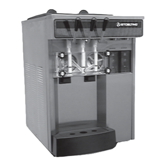
SECTION 1 INTRODUCTION 1.1 DESCRIPTION The Stoelting Endura/Futura 131 counter freezer is gravity fed. The freezer is equipped with fully automatic controls to provide a uniform product. The freezer is designed to operate with almost any type of commercial soft serve or non-dairy mixes available, including ice milk, ice cream, yogurt, and frozen dietary desserts. - Page 10 MODEL ENDURA/FUTURA 131 COUNTER MODEL GRAVITY FREEZER Dimensions: Freezer: 22" (56 cm) wide x 28" (72 cm) deep x 34.75" (88 cm) high Crated: 28" (71 cm) wide x 35" (89 cm) deep x 38" (96 cm) high Weight: Freezer: 370 lbs.
-
Page 11: Installation Instructions
Take notice of all warning labels on the freezer (Fig. 3). STOELTING, INC. The labels have been put there to help maintain a safe ATTENTION: Customer Service working environment. -
Page 12: Shipment And Transit
If concealed damaged and/or shortage is found later, advise the carrier within 10 days and request inspection. The customer must place claim for damages and/or shortages in shipment with the carrier. Stoelting, Inc. cannot make any claims against the carrier. FREEZER INSTALLATION... -
Page 13: Floor Stand Installation
FLOOR STAND INSTALLATION INSTALLING PERMANENT WIRING To install the E/F 131 on to the floor stand, follow the steps outlined below: WARNING ELECTRICAL TECHNICIANS MUST BE 1. Uncrate the floor stand and place in an upright CONTINUOUSLY ALERT TO THE PRACTICE position. -
Page 15: Initial Set-Up And Operation
SECTION 3 INITIAL SET-UP AND OPERATION 3.1 OPERATOR'S SAFETY PRECAUTIONS 3.2 OPERATION CONTROLS AND INDICATORS SAFE OPERATION IS NOT AN ACCIDENT; Observe Before operating the freezer, it is required that the these rules: operator know the function of each operating control. -
Page 16: Sanitizing
C. PUSH TO FREEZE SWITCH NOTE The PUSH TO FREEZE switch is a "snap" switch Failure to immediately refill hopper may result in opera- used to start the freezing cycle. During initial freeze tional problems. down, the OFF-ON switch is placed in the ON position. -
Page 17: Freeze Down And Operation
In general, sanitizing may be conducted as follows: D. Clean sides of hopper, mix inlet regulator and under- side of hopper cover using a sanitized soft bristle A. Push the mix inlet regulator into hopper with air inlet brush dipped in the sanitizing solution (Fig. 13). (long) tube toward the front of the freezer. -
Page 18: Mix Information
D. Fill hopper with approximately 3 gallons (11.4 liters) I. The freezer is designed to dispense the product at a of prechilled (40°F or 4°C) mix. reasonable draw rate. If the freezer is overdrawn, the result is a soft product or a product that will not CAUTION dispense at all. -
Page 19: Removing Mix Inlet Regulator
3.6 REMOVING MIX FROM THE FREEZER After the mix has been removed from the freezer, the To remove the mix from the freezer, refer to the following freezer must be cleaned. To clean the freezer, refer to the steps: following steps: A. -
Page 20: Removing Front Door
To disassemble the freezer, refer to the following steps: A. Remove the mix inlet regulator from the hopper by pulling straight up. B. Remove the front door by turning off the circular knobs and then pulling the front door off the studs (Fig.19). -
Page 21: Cleaning The Freezer Parts
B. Place all parts in the sanitizing solution, then remove and let air dry. C. Using this sanitizing solution and the large barrel brush provided, sanitize the rear of the barrel and drive area by dipping the brush in the sanitizing solution and brushing the rear of the barrel. -
Page 22: Routine Cleaning
CAUTION DO NOT PLACE THE MIX INLET REGULATOR INTO THE HOPPER BEFORE INSTALLING THE AUGER. E. Install the two plastic flights onto rear of the auger and insert part way into freezer barrel. F. Install the third plastic flight, push the auger into the freezer barrel and rotate slowly until the auger engages the drive socket. - Page 23 Once milkstone has formed, it is very difficult to Proper Daily Maintenance: The Only Way to remove. Without using the correct product and Assure Food Safety and Product Quality procedure, it is nearly impossible to remove a thick Proper daily maintenance can involve a wide variety layer of milkstone.
-
Page 24: Extended Storage
PRODUCT SAFETY – Strong acids are Sanitizing solutions should not be allowed to fall below dangerous chemicals and handling them 100 ppm chlorine. New solutions should be mixed once requires safety. old solutions become ineffective. WARNING MACHINE DAMAGE – Strong acids will attack metal and rubber causing premature wear of NEVER ATTEMPT TO REPAIR OR PERFORM parts. -
Page 25: Refrigeration System
SECTION 4 REFRIGERATION SYSTEM WARNING REFRIGERATION SYSTEM BOTH SUCTION SIDE SOLENOIDS MUST BE ACTIVATED FOR PROPER PURGING OF The refrigeration system (Fig.27) is a dual-purpose SYSTEM. USE POWER CORD PART NUMBER system. 430119 OR EQUIVALENT FOR DIRECT CONNECTION. Figure 27. Refrigeration System... -
Page 26: Evaporators
The system is designed to operate both the hopper and 3. Remove wires C, R, and S at compressor. Refer to evaporator simultaneously at different temperatures. Figure 29 for compressor connections. The system is designed for efficient use with R404A as the refrigerant. -
Page 27: Condensers
5. Connect the ohmmeter to terminals C and S. ventilation on the right and left sides of the unit for free flow Resistance through the start winding should be 7.77 of air (Figure 32). Make sure the freezer is not pulling over to 8.93 ohms with the ohmmeter set at ohms x 1. -
Page 28: Adjustment
T.X.V. A T.X.V. (Thermostatic Expansion Valve) (Figure 34) is used to meter the refrigerant to the evaporator. The self-regulating T.X.V. is preset at the factory. Figure 34. T.X.V. (Thermostatic Expansion Valve) Figure 33. Condenser Inspection T.X.V. ADJUSTMENT 4. If the condenser is dirty, place a wet towel over the T.X.V. -
Page 29: Installation
7. Unsweat the suction line and liquid line from the T.X.V. and remove. T.X.V. INSTALLATION To replace the T.X.V., perform the following proce- dures: CAUTION WHEN PLACING THE T.X.V., A HEATSINK (WET CLOTH) MUST BE USED TO PREVENT DAMAGE TO THE VALVE. 1. -
Page 30: Hopper
6. Install the bulb on the suction line exiting the HOPPER evaporator (Figure 37). The T.X.V. bulb should always be mounted on the top of the horizontal line. Good contact between the bulb and suction line is A parallel refrigeration circuit feeds the hoppers. A necessary for proper operation of the valve. -
Page 31: Removal
NOTE 4.11 E.P.R. REMOVAL The ideal E.P.R. valve setting (69-71 P.S.I.G.) will not allow mix to freeze to the walls of the hopper. CAUTION A HEATSINK (WET CLOTH) MUST BE USED 5. If the pressure gauge reading does not fall between TO PREVENT DAMAGE TO THE VALVE. -
Page 32: Capillary Tubes
1. Position the E.P.R. valve, with heatsink, so hopper 4.13 CAPILLARY TUBES evaporator outlet line and the line leading to the low side of the system correspond with the proper valve Capillary tube replacement may be necessary if the ports (Figure 41). correct hopper cooling cannot be obtained. -
Page 33: Solenoid Valve
2. Position the capillary tube and braze the tube to the NOTE hopper using the appropriate material. (Figure 43) Freezer barrels must not contain frozen product for this test. 1. To check the suction line solenoid valve seats, we must keep the liquid line solenoid open. Use power cord, Part No. -
Page 34: Solenoid Magnetic Coil Removal
4.18 SOLENOID MAGNETIC COIL INSTALLATION To replace the magnetic coil, perform the following procedures: 1. Push the magnetic coil on the solenoid body and replace the retainer. 2. Connect the two electrical wires. 4.19 LIQUID AND SUCTION LINE SOLENOID VALVE REMOVAL Figure 46. -
Page 35: Liquid And Suction Line Solenoid Valve Installation
6. Apply a heatsink (wet cloth) to the valve body and 3. Remove the cap from the high side Schrader access unsweat the two joints. Remove the valve body. fitting and install a 0-500 P.S.I.G. gauge. 4.20 LIQUID AND SUCTION LINE 4. -
Page 36: Water Valve Installation
1. Turn off and disconnect the water supply and drain. 8. Replace all panels. Blow out the water lines with compressed air or CO2. 4.25 REFRIGERANT CHARGE (ALL MODELS) 2. Recover the refrigerant charge, then leave a port to open to prevent pressure buildup when applying heat. The following symptoms will occur if there is a slow leak in the system: 3. -
Page 37: Controls
SECTION 5 CONTROLS CONTROL SYSTEM TYPE 4 contactors. The power board has a third relay; it is used to transfer power to control the liquid line solenoid valve. The relay will close after 2 hours of red light idle causing The control system is the brain of the freezer. -
Page 38: Power Board
Figure 51. Power Board... - Page 39 Figure 52. Program Module...
-
Page 40: Membrane Switch Panel Display Board
Figure 53. Membrane Switch Panel Display Board When the cycle switch SW1 is placed in the ) start at the end of the set off time. The freezer position, the control will go through a self-test will remain on until brought to consistency. After sequence and the results will be displayed the selected number of operating cycles, the control will operate in idle mode strictly by On/... - Page 41 E. Control Calibration NOTE Values below are default values only. Values for your freezer can be found inside the decorative header panel or in the information packet behind the left side panel DIGIT DISPLAY WORD PUSH BUTTON NOTES FUNCTION ACTION NOTE Self-Test Push-button actuation enters...
- Page 42 DIGIT DISPLAY WORD NOTES PUSH BUTTON FUNCTION ACTION Ninth push-button actuation Rotate calibrate to adjust Hopper Temp. hopper temperature set point 25 Used for separate hopper - 45°F (-4+7°C). °F refrigeration system only. Tenth push-button actuation Rotate calibrate to adjust Barrel Temp.
- Page 43 F. Error Conditions Spigot Switch. The Spigot Switch is a normally closed held open switch. When the spigot is opened, the switch will close starting the freezer. When the rotary switch SW1 is rotated to the Self-Test position (calibrate “0”), the control will be in the test mode.
-
Page 44: Plug-In Relays
H. Freezer Operation and run until the preset barrel temperature is reached, then after the preset On time, stop. When the spigot is opened, the drive will start Consistency Mode. When the Off/On Switch is immediately and the compressor 3-4 seconds placed in the On position, the red Push-To- later. -
Page 45: Spigot Switches
SPIGOT SWITCHES SPIGOT SWITCH INSTALLATION 1. Install the replacement switch onto the handle The spigot switch will automatically actuate the auger assembly. Do not fully tighten the retaining screws drive and refrigeration system when the spigot is opened at this time. to dispense product. -
Page 46: Front Door Interlock Switch Assembly
5. Remove the two electrical wires from the interlock 4. Attach the two electrical wires to the common and switch (Figure 56). normally open terminals. 5. Position the spigot handle assemblies in the electrical box and secure with the Phillips head screws. 6. -
Page 47: Touch Pad Switch Module Assembly
5.14 TOUCH PAD SWITCH MODULE ASSEMBLY 1. Position the circuit board on the new module and secure with the four screws. 2. Insert the ribbon into the connector and close the hinged portion of the connector. CAUTION THE CUTOUTS IN THE RIBBON MUST LINE UP WITH THE PRONGS ON THE HINGED PORTION OF THE CONNECTOR BEFORE Figure 59. -
Page 48: Sensor Installation
5. Carefully remove the foam and thermal mastic until 8. Replace all panels. the sensor is visible, then cut the small ty-raps that hold the sensor, and remove (Figure 62). 5.18 PREPARATION FOR MAJOR COMPONENT REMOVAL The procedure set forth in this section must be followed completely and in the order in which they appear. -
Page 49: Condenser Fan Motor Installation
6. Slide the fan blade off the motor shaft and remove the fan motor and bracket from the freezer. 7. Remove the fan motor from the bracket. 5.21 CONDENSER FAN MOTOR INSTALLATION 1. Install the replacement fan motor onto the bracket and secure with the three hex nuts and washers. -
Page 50: Drive Motor Installation
1. Loosen the belt tension adjusting nut and remove the 5.24 DRIVE MOTOR INSTALLATION drive belt (Figure 65). 1. Fit the key and pulley to the replacement motor. 2. Remove the cover plate and connect the four electrical wires, the replace the cover plate. 3. -
Page 51: Speed Reducer
5.25 SPEED REDUCER 5.27 SPEED REDUCER INSTALLATION The speed reducer is a heavy duty sealed unit that does 1. Assemble the pulley and key onto the replacement not require any maintenance. speed reducer. Do not fully tighten setscrew. 5.26 SPEED REDUCER REMOVAL 2. -
Page 52: Compressor
4. Remove 6” of insulating tubing on the suction line 5.28 COMPRESSOR going to the compressor and unsweat the suction and discharge line from the compressor. The compressor is designed specifically for use with R404A. It has an internal high-pressure bypass. This 5. -
Page 53: Final Assembly Of Freezer
CAUTION 11.Purge and evacuate the refrigeration system to 50 microns of mercury for approximately 30 minutes. IF ACID HAS BEEN FOUND IN THE COMPRESSOR SYSTEM. CLEAN OUT PER THE COMPRESSOR MANUFACTURER’S 12.Accurately charge the system with R22 per the INSTRUCTIONS. amount indicated on the specification tag located on the top front of the right side panel. -
Page 55: Troubleshooting
Environmental Protection Agency requirements per the provisions of the U.S. Clean Air Act. In the event the Troubleshooting Guide does not help to correct the service problem, the factory Service Department should be contacted. Contact: STOELTING, INC. Phone: 920-894-2293 502 Hwy. 67... -
Page 56: Dispensing, Servability And Overrun
6.3.16 Freezer will not leave present mode 6.3.17 Touch Pad lights do not work; freezer operates normally 6.3.18 Compressor discharge pressure too high 6.3.19 Compressor running too hot; trips on overload protector 6.3.20 Compressor suction pressure too high 6.3.21 Compressor suction pressure too low 6.3.22 Freezer refrigerant charge is low 6.4 Control Displayed... -
Page 57: Barrel And Hopper Mix Temperature Maintenance
Control ‘LKG’ temperature is too high/low....Control ‘LKG’ temperature should approximately equal or ..................slightly exceed the desired product serving temperature; ..................change accordingly (refer to control setup procedure in ..................subsection 3.2). Mix inlet regulator leaking air and/or mix...... Check and/or replace missing, worn, or damaged o-rings .................. -
Page 58: Electro-Mechanical
6.2.2 FROZEN PRODUCT ON HOPPER WALLS CAUSE CORRECTION Heavy freezer usage ............. There is no correction required if the E.P.R. valve setting is ..................correct. Some product freezing to the walls during heavy freezer ..................operation is normal. E.P.R. valve needs adjusting........Make appropriate adjustment. Refer to Refrigeration Section 4, .................. - Page 59 6.3.3 RED CLEAN LIGHT IS FLASHING CAUSE CORRECTION CLEAN was deactivated by depressing the CLEAN switch; control is awaiting your next command ..............Turn power OFF then ON to leave CLEAN mode or depress ode operation..................CLEAN again to continue CLEAN m 6.3.4 HOLD READY SWITCH WILL NOT WORK CAUSE CORRECTION...
- Page 60 6.3.8 COMPRESSOR STARTS AND RUNS, BUT SHORT CYCLES ON OVERLOAD PROTECTOR CAUSE CORRECTION Low voltage to unit ............Determine reason and correct. Improperly wired ............Check wiring against diagram. Overload protector defective ......... Replace overload protector. Capacitor defective ............Check start/run capacitor. Replace if defective. Excessively high discharge pressure ......
- Page 61 6.3.13 FREEZER REFREEZES TOO OFTEN IN GREEN LIGHT MODE CAUSE CORRECTION Ambient temperature is high ......... Move or direct hot air away from freezer. Control ‘LKG’ temperature is too high/low ....Control ‘LKG’ temperature should approximately equal or slightly ..................exceed the desired product serving temperature; change accord- ..................
- Page 62 Freezer located near heat source ......... Move or direct hot air away from freezer. Ambient temperature is high ......... Same as above. Freezer discharge air recirculating into condenser intake ............Eliminate recirculating using Stoelting top rear air discharge ..................plenum. Dirty condenser and/or filter .......... *Clear condenser.
- Page 63 6.3.20 COMPRESSOR SUCTION PRESSURE TOO HIGH CAUSE CORRECTION Expansion valve setting grossly out of adjustment ..............*Replace expansion valve. NOTE Expansion valve setting is preset for optimum balance of flow to barrel and hopper- DO NOT ATTEMPT TO ADJUST THE VALVE SETTING. Refrigerant overcharge ..........
-
Page 64: Control Displayed Error Conditions
..................STEP 2: Empty barrel and hopper of all product. Rinse hopper ..................and barrel with cool water using a sanitized bucket. Refill freezer ..................with 35° to 45° mix until hopper is full with mix inlet regulator in ..................place. Upon freeze-down, the sightglass should clear within the .................. - Page 65 6.4.7 ERROR 07: DRIVE MOTOR (P.T.F. LIGHT FLASHES IN SEQUENCE OF SEVEN) CAUSE CORRECTION Drive motor overload is open........Determine cause for overload. Wait 15 to 20 minutes for auto- ..................matic reset of overload. Turn power OFF then ON to clear error ..................
-
Page 67: Replacement Parts
SECTION 7 REPLACEMENT PARTS B. Serial number of model, stamped on nameplate. HOW TO ORDER PARTS To assure receipt of the proper replacement parts, C. Part number , p art name and quantity needed. supply your dealer or distributor with the following Common part names and numbers are listed in this information: manual.
Need help?
Do you have a question about the Endura 131 and is the answer not in the manual?
Questions and answers