Sign In
Upload
Download
Table of Contents
Contents
Add to my manuals
Delete from my manuals
Share
URL of this page:
HTML Link:
Bookmark this page
Add
Manual will be automatically added to "My Manuals"
Print this page
×
Bookmark added
×
Added to my manuals
Manuals
Brands
Stoelting Manuals
Freezer
E157
Service manual
Stoelting E157 Service Manual
Slush freezer
Hide thumbs
Also See for E157
:
Owner's manual
(39 pages)
1
2
3
4
Table Of Contents
5
6
7
8
9
10
11
12
13
14
15
16
17
18
19
20
21
22
23
24
25
26
27
28
29
30
31
32
33
34
35
36
37
38
39
40
41
42
43
44
45
46
47
48
49
50
51
52
page
of
52
Go
/
52
Contents
Table of Contents
Troubleshooting
Bookmarks
Table of Contents
Table of Contents
Introduction
Descriptions
Section 1 Introduction
Specifications
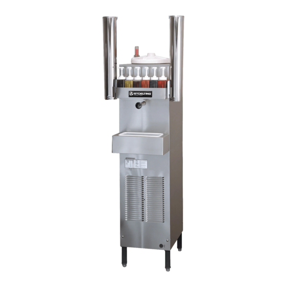
Model E157 - Front
Model E157 - Side
Freezer Installation
Safety Precautions
Section 2 Installation Instructions
Shipment and Transit
Adjustable Leg
Installation Instructions
Warning Label Locations - E157
Space & Ventilation Requirements
Electrical Plug
Installing Drip Tray and Cover
Adjusting Cup Dispensers
Initial Set-Up and Operation
Operator's Safety Precautions
Operating Controls and Indicators
Draining the Freezer for Disassembling and Cleaning
Disassembly and Cleaning of Freezer Parts
Draining Product
Removing Spigot Assembly
Removing Spigot O-Ring from Spigot Body
Cut-Away View of Spigot Assembly
Removing Drive Cap and O-Ring
Removing Sealer Ring
Removing Agitator Assembly and Lower Bushing
Removing Divider Plate from Agitator Fingers
Removing Drive Shaft
Sanitizing the Freezers and Freezer Parts
Assembly of Freezer
Lubricating Drive Shaft
Correct and Incorrect Alignment of Vertical Center Post Guide Hole
MIX Information
Freeze down and Operation
Dispensing Product
Routine Cleaning
Preventative Maintenance
Extended Storage
Installing Divider Plate and Agitator Assembly
Proper Installation of Sealer Ring
External Parts to be Cleaned
Decals and Tags
How to Order Decals and Tags
Check Winding
Check Winding to Ground
Refrigerant Components and Adjustments
Refrigeration System
Compressor
Condenser
Check Condenser
Remove Cap
Install Gauge
Adjust A.X.V
Filter Drier Replacement
Tension Spring
Electrical System Operation and Adjustments
Hour Timer
Electronic Torque Control
Removing Torque Control
Disconnect Wire
Compressor Installation
Compressor Removal
Major Component Removal and Installation
Introduction
Condenser Fan Removal
Drive Motor Removal
Compressor Removal
Install Compressor
Drive Motor Installation
Condenser Fan Installation
Remove Filter Drier
Tension Spring
Section 8 Troubleshooting
Compressor Relay Defective or Burned out
Compressor Run Capacitor Open, Shorted, or Blown
Compressor Runs Continuously
Compressor Starts and Runs, but Short Cycles on Overload Protector
Compressor will Not Start
Unit Noisy
Troubleshooting
Compressor will Not Start - Hums but Trips on Overload Protector
Compressor Starts, but Does Not Switch off of Start Windings
Compressor Start Capacitor Open, Shorted or Blown
Freezer will Not Start
Drive Motor Overload Trips (Freezer Shuts down When Running)
Compressor will Not Run, but Drive Motor Runs
Product Dispenses Incorrectly
Product Is too Thin
Agitator Does Not Rotate
No Ice Crystals on Initial Freeze down
Excessive Ice Crystals above Divider Plate
Spigot Leaking or Stuck
Replacement Parts and Reference Drawings
How to Order Parts
Spigot Assembly Parts
Exploded View of Spigot Assembly
Model E157 Exploded View
Model E157 Parts List
Model E257 Exploded View
Model E257 Parts List
Model F257 Exploded View
Model F257 Parts List
Advertisement
Quick Links
1
Initial Set-Up and Operation
2
Model E257 Exploded View
3
Model E257 Parts List
Download this manual
See also:
Owner's Manual
Model E157/E257/F257
SERVICE MANUAL
Manual No. 513565 Rev.2
June, 2003
Table of
Contents
Previous
Page
Next
Page
1
2
3
4
5
Advertisement
Table of Contents
Need help?
Do you have a question about the E157 and is the answer not in the manual?
Ask a question
Questions and answers
Related Manuals for Stoelting E157
Freezer Stoelting E157 Owner's Manual
Slush freezers (39 pages)
Freezer Stoelting E257 Service Manual
Slush freezer (52 pages)
Freezer Stoelting E112 Owner's Manual
Counter model gravity freezer shake and frozen beverage (27 pages)
Freezer Stoelting F112 Owner's Manual
Counter freezers (31 pages)
Freezer Stoelting E112 Operator's Manual
(32 pages)
Freezer Stoelting Endura 111 Owner's Manual
Counter model gravity freezer soft serve (33 pages)
Freezer Stoelting Endura 131 Service Manual
(80 pages)
Freezer stoelting E122 Operator's Manual
Counter top shake or frozen beverage freezer (40 pages)
Freezer Stoelting E131I Owner's Manual
(37 pages)
Freezer Stoelting O111 Owner's Manual
Intellitec counter model gravity freezer shake and frozen beverage (31 pages)
Freezer Stoelting F431 Owner's Manual
Cab model soft-serve pressurized freezer (43 pages)
Freezer Stoelting VB25 Freezer Operating Manual
Vb25 freezer operating manual (24 pages)
Freezer Stoelting U431 Owner's Manual
Cab model soft-serve pressurized freezer (51 pages)
Freezer Stoelting Futura F131 Owner's Manual
Counter model gravity freezer soft serve/shake (37 pages)
Freezer Stoelting 4231G Owner's Manual
Floor gravity freezer soft-serve (43 pages)
Freezer Stoelting Optima SO218 Owner's Manual
Floor model freezer (29 pages)
This manual is also suitable for:
F257
E257
Table of Contents
Print
Rename the bookmark
Delete bookmark?
Delete from my manuals?
Login
Sign In
OR
Sign in with Facebook
Sign in with Google
Upload manual
Upload from disk
Upload from URL


Need help?
Do you have a question about the E157 and is the answer not in the manual?
Questions and answers