Table of Contents
Advertisement
Quick Links
Advertisement
Table of Contents
Troubleshooting

Subscribe to Our Youtube Channel
Related Manuals for Stoelting O411


Summary of Contents for Stoelting O411
- Page 1 Model O411 OPERATORS MANUAL Manual No. 513626 Rev.3...
- Page 3 DO NOT ATTEMPT to operate the machine until instructions and safety precautions in this manual are read completely and are thoroughly understood. If problems develop or questions arise in connection with installation, operation, or servicing of the machine, contact Stoelting. Stoelting Foodservice Equipment Customer Service: 888.429.5920...
-
Page 4: Safety Information
CAUTION If you need to replace a part, use genuine Stoelting The signal word “CAUTION” indicates a potentially parts with the correct part number or an equivalent hazardous situation, which, if not avoided, may result part. -
Page 5: Table Of Contents
TABLE OF CONTENTS Section Description Page Description and Specifi cations Description ....................1 Specifi cations ..................... 2 Installation Instructions Safety Precautions ..................3 Shipment and Transit .................. 3 Machine Installation ..................3 Installing Permanent Wiring ................ 3 Mix Pump ....................4 Mix Pump Hose Installation.................. - Page 6 Section Description Page Maintenance and Adjustments Machine Adjustment ................... 17 Product Consistency Adjustment ..............17 Locking the Control Panel ................17 Obtaining Readings and Modifying Settings (Service Personnel Only) ..17 Readings (Service Personnel Only) ............18 Adjustments (Service Personnel Only) ............19 Other Settings (Service Personnel Only) ............
-
Page 7: Description And Specifi Cations
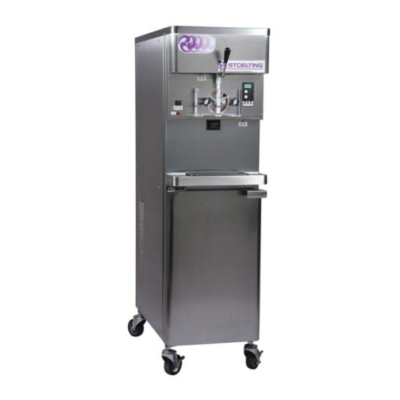
SECTION 1 DESCRIPTION AND SPECIFICATIONS 1.1 DESCRIPTION The Stoelting O411 fl oor model machine is pressure fed. The machine is equipped with fully automatic controls to provide a uniform product. The machine is designed to operate with almost any type of commercial soft-serve or non-dairy mixes available, including ice milk, ice cream, yogurt, and frozen dietary desserts. -
Page 8: Specifi Cations
1.2 SPECIFICATIONS Model O411 Dimensions Machine with crate width 19-1/2’’ (49,5 cm) 27’’ (68,6 cm) height 67’’ (170,2 cm) 78’’ (198,1 cm) depth 38-1/4’’ (97,2 cm) 48’’ (121,9 cm) Weight 450 lbs (204,1 kg) 650 lbs (294,8 kg) Electrical 1 Phase, 208-240 VAC, 60Hz... -
Page 9: Installation Instructions
10 days and request inspection. The customer must place a claim for damages and/or short- ages in shipment with the carrier. Stoelting, Inc. cannot make any claims against the carrier. 2.3 MACHINE INSTALLATION... -
Page 10: Mix Pump
B. MIX PICKUP HOSE INSTALLATION Allow the hose to feed itself through the pump until about 6” (15cm) remains on the entering The O411 machine may be connected to the standard mix side. container or up to three prepacked mix bags. Follow the instructions below that match your confi... - Page 11 Figure 2-3 Mix Pump Connections for Standard Mix Container Connect the free end of the tubing to the mix check Slide the hose clip over free end of 3/8” (9,5mm) valve. Observe the direction of the check valve ID plastic food grade tubing. Attach the free end fl...
-
Page 12: Mix Low Level Indicator Adjustment
Place three mix bags into the mix container. C. MIX LOW LEVEL INDICATOR ADJUSTMENT Connect the bag adapter attached to the left side The sensitivity of the “Mix Low” indication that displays on of the manifold (closest to the mix outlet) to the the control panel can be adjusted to operator preference. -
Page 13: Initial Set-Up And Operation
When the switch is in the ON position, the noise or vibration occurs. machine will be operational. Freezing Dispense Cylinder Off/On Rate Adjustor IntelliTec Control Main Freezer (See Figure 3-2) Power Off/On Pump Power Off/On Cab Off Indicator Light Figure 3-1 O411 Controls... - Page 14 C. SPIGOT SWITCH J. DRIVE MOTOR OVERLOAD The spigot switch is mounted to the spigot cam assembly The internal drive motor overload will trip if the drive behind the header panel. When the spigot is opened to motor is overloaded. It will reset after approximately 10- dispense product, the spigot switch opens and the “Serve 12 minutes.
-
Page 15: Disassembly Of Machine Parts
3.3 DISASSEMBLY OF MACHINE PARTS WARNING Moving machinery can grab, mangle and dismem- ber. Place the Main Freezer Power Off/On switch in the OFF position before disassembling for cleaning or servicing. Before using the machine for the fi rst time, complete machine disassembly, cleaning and sanitizing proce- dures need to be followed. -
Page 16: Cleaning Disassembled Parts
3.4 CLEANING DISASSEMBLED PARTS 3.7 ASSEMBLING MACHINE Disassembled machine parts require complete cleaning, To assemble the machine parts, refer to the following steps: sanitizing and air drying before assembling. Local and state NOTICE health codes will dictate the procedure required. Some Petrol-Gel sanitary lubricant or equivalent must be state health codes require a four sink process (pre-wash, used when lubrication of machine parts is specifi... -
Page 17: Sanitizing
When sanitizing the machine, refer to local sanitary regu- lations for applicable codes and recommended sanitizing products and procedures. The frequency of sanitizing must comply with local health regulations. Mix sanitizer according to manufacturer’s instructions to provide a 100 parts per million strength solution. Mix sanitizer in quanti- ties of no less than 2 gallons of 90°F to 110°F (32°C to 43°C) water. -
Page 18: Initial Freeze Down And Operation
“°F” and “amps” readings. 3.9 INITIAL FREEZE DOWN AND OPERATION C. INITIAL FREEZE DOWN Every Stoelting soft serve machine needs to be set on site. Place the Freezing Cylinder OFF/ON switch in The following adjustment will provide optimal product the ON position. -
Page 19: Serving Product
Press the SEL button. The LCD will read “CutOut Place a container under the spigot and open the amps” along with the programmed value from the spigot to allow the mix to fl ush out about 8 ounces previous step. (0.23 liters) of sanitizing solution and liquid mix. -
Page 20: Operation Of Mix Pump
Old mix, or mix that has been stored at too high a tempera- Air Operation: The air compressor operates ture, can result in a fi nished product that is unsatisfactory. whenever the peristaltic mix pump is running. To retard bacteria growth in dairy based mixes, the best Air enters through a check valve on the piston storage temperature range is between 33°... -
Page 21: Disassembly And Inspection Of Removable Parts
3.14 DISASSEMBLY AND INSPECTION OF REMOVABLE PARTS Inspection of removable parts should be made whenever maintenance is performed or when the pump requires disassembly. NOTE If the mix line or air line is diffi cult to remove, soften the tubing with a rag soaked in hot water. Hose connections may be sprayed with Haynes Sanitary Lubricant for ease of removal. -
Page 23: Maintenance And Adjustments
SECTION 4 MAINTENANCE AND ADJUSTMENTS MACHINE ADJUSTMENT LOCKING THE CONTROL PANEL This section is intended to provide maintenance personnel The IntelliTec control has a tamper proof mode to prevent with a general understanding of the machine adjustments. unauthorized use. When set, all buttons on the control It is recommended that any adjustments in this section panel are disabled. -
Page 24: Readings (Service Personnel Only)
IMPORTANT: Supply V (VAC) Before making changes to any settings, record A calculated input voltage is recorded. the original values. If the setting changes do not ERROR CODE READINGS achieve desired results, return settings to their The following details are recorded under the ERRCODES original values. -
Page 25: Adjustments (Service Personnel Only)
RUN STATISTICS Cut In T (°F) In addition to dynamic readings and recorded After the consistency value has been determined, error code details, the IntelliTec control records the Cut In T value can be adjusted. The Cut In rolling averages of run statistics. Following are the T is the temperature of the refrigerant gas in the readings available under the RUNSTATS menu: evaporator at the front of the freezing cylinder. -
Page 26: Overrun Adjustment
40% overrun. Because of the storage refrigeration cycle. The setting for differences in mix formulation, temperatures and baro- the O411 is Cabinet. metric pressure, this fi gure may vary. It will be necessary CabCutIn (°F) for approximately 2 gallons of mix to be pumped through... -
Page 27: Mix Pump Hose Reposition
Turn the mix pump switch to the OFF position. Disconnect power sources/circuit breakers. Remove the back panel from the machine. On the air compressor side of the pump, locate the long/slender piston rocking arm. The rocking arm downward travel is limited by a stationery cam. -
Page 28: Cab Temperature Adjustment
Feed one end of the mix pump hose into the Press the left arrow button () three (3) times to pickup hose side (left) of the black cover. navigate to the Storage menu. NOTE Press the up arrow button () once to navigate to the CabCutIn value. -
Page 29: Condenser Cleaning (Air-Cooled Machines)
When the tension is properly adjusted, the belt The United States Department of Agriculture and the Food will depress the approximate width of the belt with and Drug Administration require that lubricants used in the pressure of a fi nger. food zones be certifi... -
Page 31: Troubleshooting Error Codes
If the error persists after attempting to clear it, Error Code 2 - High Torque contact your Authorized Stoelting Distributor for If the control panel displays a High Torque Error further assistance. (E2), the controller has sensed that the drive... - Page 32 Cylinder Off-On switch in the Off position and back On position. If the error persists, contact your in the On position. If the error persists, contact Authorized Stoelting Distributor for further your Authorized Stoelting Distributor for further assistance. assistance. Error Code 11 - Low Temperature...
-
Page 33: Troubleshooting - Machine
5.3 TROUBLESHOOTING - MACHINE PROBLEM POSSIBLE CAUSE REMEDY 1. Power to machine is off. 1. Check power to machine. Drive motor (auger) 2. Low line voltage. 2. Check, must be ±10% of nameplate voltage. “kicks-out”, or 3. Product too hard. 3. -
Page 34: Troubleshooting - Mix Pump
1. Increase overrun setting. 2. Air leak. 2. Tighten all hose clamps. Overrun too low or no overrun. 3. Air compressor not pumping air. 3. Contact local Stoelting Distributor. 4. Air check valve in backwards. 4. Check arrow for direction of fl ow. - Page 35 4. Pump motor not running. 4. Turn on motor switch. Air exiting mix pick- 1. Pickup tube check valve missing. 1. Contact local Stoelting Distributor. up hose. 1. Overrun setting too high. 1. Decrease overrun setting. 2. Mix pump hose service life is 2.
-
Page 37: Replacement Parts
Decal - Attention Heat Sensitive 324686 Decal - Danger Automatic Start 324728 Decal - Contactor Identifi cation 324803 Decal - Domed Stoelting Logo (Large) (Header Panel) 324804 Decal - Domed Stoelting Swirl (Header Panel) 324825 Decal - Main Freezer Power 324826... -
Page 38: Auger Shaft And Faceplate Parts
6.3 AUGER SHAFT AND FACEPLATE PARTS Part Description Quantity 149003 Bushing - Front Auger Support 381804 Auger Flight 417006 Grid - Drip Tray 482004 Knob - Air Bleed Valve 624520 O-Ring - Air Bleed Valve - Black (5 Pack) 624598 O-Ring - Spigot Body - Black (5 Pack) 624678 O-Ring - Rear Seal &... -
Page 39: Cab Tubing Assembly
6.4 CAB TUBING ASSEMBLY Part Number Description Quantity 264235 Clamp - Metal (1/4” ID Tubing) (Cab) 264241 Clamp - Metal (1/2” ID Tubing) (Cab) 264243 Clamp - Metal (3/8” ID Tubing) (Cab) 375819 Elbow - Barbed (3/8”- 1/4”) (Cab) 376041 Tee Connector - 3-Way (Stainless) (Cab) 558109 Mix Container Only (Cab) - Page 41 Stoelting, LLC warrants to the first user (the “Buyer”) that the freezer cylinders, hoppers, compressors, drive motors, speed reducers, augers and auger flights of Stoelting soft serve / shake freezers will be free from defects in materials and workmanship under normal use and proper maintenance appearing within five (5) years, and that...
Need help?
Do you have a question about the O411 and is the answer not in the manual?
Questions and answers