Table of Contents
Advertisement
Quick Links
Advertisement
Table of Contents
Troubleshooting

Related Manuals for Stoelting SU444 Series


Summary of Contents for Stoelting SU444 Series
- Page 1 Model SU444 OPERATORS MANUAL Manual No. 513639 Rev.3...
- Page 3 DO NOT ATTEMPT to operate the machine until instructions and safety precautions in this manual are read completely and are thoroughly understood. If problems develop or questions arise in connection with installation, operation, or servicing of the machine, contact Stoelting. Stoelting Foodservice Equipment Customer Service: 888.429.5920...
-
Page 4: Safety Information
CAUTION If you need to replace a part, use genuine Stoelting The signal word “CAUTION” indicates a potentially parts with the correct part number or an equivalent hazardous situation, which, if not avoided, may result part. -
Page 5: Table Of Contents
TABLE OF CONTENTS Section Description Page Description and Specifi cations Description ....................1 Specifi cations ..................... 2 Installation Instructions Safety Precautions ..................3 Shipment and Transit .................. 3 Machine Installation ..................3 Installing Permanent Wiring ................ 3 Check Check Compressor for Proper Power ..........4 Check Blender Rotation ................ - Page 6 Section Description Page Maintenance and Adjustments Machine Adjustment ................... 19 Product Temperature Adjustment (Left Side) ..........19 Product Consistency Adjustment (Right Side) ..........19 Locking the Control Panel (Right Side) ............19 Obtaining Readings and Modifying Settings (Service Personnel Only) (Right Side) ............19 Readings (Service Personnel Only) (Right Side) ........
-
Page 7: Description And Specifi Cations
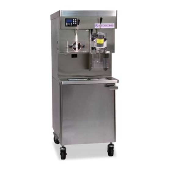
SECTION 1 DESCRIPTION AND SPECIFICATIONS DESCRIPTION The Stoelting SU444 and U444A fl oor model machines are pressure fed. They are equipped with fully automatic controls to provide a uniform product. The SU444 and U444A are designed to dispense soft serve product from the left side and shake product from the right side. -
Page 8: Specifi Cations
SPECIFICATIONS SU444 Water Cooled SU444 Air Cooled Dimensions Machine with crate Machine with crate width 26-7/8’’ (68,3 cm) 34’’ (86,4 cm) 26-7/8’’ (68,3 cm) 34’’ (86,4 cm) height 67-3/8’’ (171,1 cm) 78’’ (198,1 cm) 67-3/8’’ (171,1 cm) 78’’ (198,1 cm) depth 40’’... -
Page 9: Installation Instructions
The unbalanced leg of customer must place a claim for damages and/or short- power (called wild or high) must be connected to ages in shipment with the carrier. Stoelting, Inc. cannot L2 in the junction box. make any claims against the carrier. -
Page 10: Check Check Compressor For Proper Power
6” (15cm) Figure 2-2 Mix Hose Installation 2.5 CHECK COMPRESSOR FOR PROPER WARNING POWER (3 PHASE ONLY) Hazardous Moving Parts After connecting the electrical, check that the compressor is operating in the proper direction. Blender shaft and agitator can grab and cause injury. -
Page 11: Mix Pickup Hose Installation
Figure 2-3 Mix Pump Connections for Standard Mix Container Allow the hose to feed itself through the pump B. MIX PICKUP HOSE INSTALLATION until about 6” (15cm) remains on the entering The machine may be connected to the standard mix side. -
Page 12: Mix Low Level Indicator Adjustment
Slide the hose clip over free end of 3/8” (9,5mm) Place the mix bag(s) into the mix container. ID plastic food grade tubing. Attach the free end Connect the bag adapter attached to the left side of the tubing to a manifold adapter. Secure with of the manifold (closest to the mix outlet) to the a large hose clamp or equivalent. -
Page 13: Initial Set-Up And Operation
SECTION 3 INITIAL SET-UP AND OPERATION 3.1 OPERATOR’S SAFETY PRECAUTIONS 3.2 OPERATING CONTROLS AND INDICATORS SAFE OPERATION IS NO ACCIDENT; observe these Before operating the machine, it is required that the op- rules: erator know the function of each operating control. Refer to Figure 3-1 for the location of the operating controls on Know the machine. - Page 14 C. FRONT DOOR SAFETY SWITCH (BOTH SIDES) K. FREEZING CYLINDER OFF/ON SWITCH (RIGHT SIDE) The front door safety switch prevents the auger from turn- ing when the front door is removed. The switch is open The Freezing Cylinder OFF/ON switch is a two position when the door is removed and closed when the door is toggle switch used to supply power to the right freezing properly installed.
-
Page 15: Important Information Regarding Cleaning And Sanitizing
Push to Freeze SOIL MATERIALS ASSOCIATED WITH FROZEN DESSERT MACHINES Green LED MILKFAT/BUTTERFAT – As components of ice-cream/ frozen custard mix, these soils will accumulate on the Amber LED interior surfaces of the machine and its parts. Fats are diffi cult to remove and help attribute to milkstone buildup. Purge/Clean Button MILKSTONE –... -
Page 16: Disassembly Of Left Side
PROPER DAILY MAINTENANCE: With proper daily use of STERA-SHEEN or its equivalent, there is no need for the use of a DELIMER. The Only Way to Assure Food Safety and Product Quality DO NOT USE BLEACH Proper daily maintenance can involve a wide variety of products and procedures. -
Page 17: Remove Front Door And Auger
A. REMOVE FRONT DOOR AND AUGER Before using the machine for the fi rst time, complete machine disassembly, cleaning and sanitizing proce- Make sure the Clean/Off/Serve switch is in the dures need to be followed. Routine cleaning intervals OFF position and procedures must comply with the local and state Remove the knobs on the front door and remove health codes. -
Page 18: Cleaning Disassembled Parts
Remove the air bleed valve by unscrewing the 3.7 SANITIZING PARTS knob while holding the valve stem from behind. Use a sanitizer, mixed according to manufacturer’s Remove the compression spring and push the instructions, to provide a 100 parts per million air bleed valve through the rear of the front door. -
Page 19: Assembling The Right Side
Secure the front door to the machine by placing Petrol-Gel the knobs on the studs and tightening until fi nger tight. Do not overtighten. Proper o-ring seal can be observed through the transparent front door. 3.10 ASSEMBLING THE RIGHT SIDE Refer to the following steps for assembling the right freezing cylinder: Hex Drive... -
Page 20: Sanitizing
Place the front door assembly on the mounting Place the CLEAN-OFF-SERVE toggle switch in studs and the push front door against the machine the CLEAN position. carefully. Check for leaks when the machine barrel is fi rst On the SU444, place the blender assembly onto pressurized with sanitizing solution. -
Page 21: Initial Freeze Down And Operation
C. INITIAL FREEZE DOWN 3.12 INITIAL FREEZE DOWN AND OPERATION Place the Freezing Cylinder OFF/ON switch in Every Stoelting machine needs to be set on site. The fol- the ON position. lowing information is for the right side and only needs to Press the PUSH TO FREEZE button. -
Page 22: Serving Product
Press the SEL button. The LCD will read “CutOut Place a container under the spigot and open it to amps” along with the programmed value from the allow the mix to fl ush out about 8 ounces (0.23 previous step. liters) of sanitizing solution and liquid mix. -
Page 23: Mix Information
3.14 MIX INFORMATION NOTE The mix pump motor is equipped with an internal Mix can vary considerably from one manufacturer to overload that will “trip”, disabling the pump when another. Differences in the amount of butterfat content the motor is overloaded. Consult the troubleshoot- and quantity and quality of other ingredients have a ing section for corrective information. -
Page 24: Disassembly And Inspection Of Removable Parts
Pump 2 gallons (7.5 liters) of 90° to 110°F (32°C CAUTION to 43°C) detergent solution through the machine. System Under Pressure The use of soft water is recommended, along with dishwashing detergents such as “Joy,” “Dawn,” Never disconnect hoses from the machine or the or equivalent. -
Page 25: Maintenance And Adjustments
SECTION 4 MAINTENANCE AND ADJUSTMENTS MACHINE ADJUSTMENT control may be set from 1 to 9. The value increases by 1 each time the up arrow button is pressed. This section is intended to provide maintenance personnel After the value reaches 9, numbering restarts at with a general understanding of machine adjustments. -
Page 26: Readings (Service Personnel Only) (Right Side)
IntelliTec Control Readings READINGS (SERVICE PERSONNEL ONLY) (RIGHT SIDE) To obtain machine readings, locate the value on the ma- chine’s menu settings sheet and follow the steps below. The IntelliTec control continuously monitors and records temperatures, voltages, amps, and error code details. Press and hold the SEL button for 8 seconds. -
Page 27: Adjustments (Service Personnel Only) (Right Side)
VAC and Mode Stor Max (°F) A calculated input voltage and mode at which The highest average cabinet temperature is the error occurred are recorded. Following are recorded. descriptions of each mode: Power On (hrs) Mode Description This value is a record of the time the machine Start of freezing cycle has been in service. -
Page 28: Overrun Adjustment
OTHER SETTINGS (SERVICE Refriger PERSONNEL ONLY) (RIGHT SIDE) This setting changes how the control handles the storage refrigeration cycle. The correct setting for Changing any setting on the IntelliTec control will alter the SU444 and U444A is Cabinet. machine operation and affect the product temperature, consistency, or life. -
Page 29: Mix Pump Hose Reposition
The mix pump has been preset at the factory to produce Tighten the allen screw, then place the wrench a product with approximately 40% overrun. Because of back in its clip. Replace the lower back panel and differences in mix formulation, temperatures and baro- secure with the four screws. -
Page 30: Mix Pump Hose Replacement
4.11 MIX PUMP HOSE REPLACEMENT Connect the free end of the mix pump hose to the 3-way Tee. When all connections are complete, Mix pump hose must be replaced when tubing cannot be the 3-way Tee must be lower than the black pump further repositioned (every four to eight weeks). -
Page 31: Drive Belt Tension Adjustment
4.13 DRIVE BELT TENSION ADJUSTMENT Using a straightedge, check that the drive motor pully is aligned with the speed reducer pulley. To check belt tension, follow the steps below: Align the pulley if necessary. Remove a side panel and the back panel. NOTE Belt life will be increased if new drive belts are tightened after two or three weeks of operation. -
Page 32: Extended Storage
4.16 EXTENDED STORAGE Refer to the following steps for winterizing the machine or for storing the machine over any long period. Clean all of the parts that come in contact with mix thoroughly with warm detergent . Rinse in clear water and dry all parts. Do not sanitize. NOTE Do not let cleaning solution stand in machine barrel or mix pump during the shutdown period. -
Page 33: Troubleshooting Error Codes (Right Side)
The Soft Error (E1) is an internal control board error If the error persists after attempting to clear it, that is logged for future analysis. The refrigeration contact your Authorized Stoelting Distributor for is never stopped and the machine will continue further assistance. - Page 34 Cylinder Off-On switch in the Off position and back On position. If the error persists, contact your in the On position. If the error persists, contact Authorized Stoelting Distributor for further your Authorized Stoelting Distributor for further assistance. assistance. Error Code 11 - Low Temperature...
-
Page 35: Troubleshooting - Machine
5.3 TROUBLESHOOTING - FREEZER PROBLEM POSSIBLE CAUSE REMEDY 1 Power to machine is off. 1 Check power to machine. Drive motor (auger) 2 Low line voltage. 2 Check, must be ±10% of nameplate voltage. “kicks-out”, or 3 Product too hard. 3 Increase overrun. - Page 36 PROBLEM POSSIBLE CAUSE REMEDY 1 Drive belt tension not correct. 1 Adjust belt tension. (See Section 4.13) Drive belts slipping 2 Worn belt(s). 2 Replace belts. or squealing. 3 Low overrun. 3 Check for air leak. 1 Temperature control set too warm. 1 Decrease CabCtOut and CabCutIn (See Mix temperature Section 4.12)
-
Page 37: Troubleshooting - Mix Pump
1 Increase overrun setting. 2 Air leak. 2 Tighten all hose clamps. Overrun too low or no overrun. 3 Air compressor not pumping air. 3 Contact local Stoelting Distributor. 4 Air check valve in backwards. 4 Check arrow for direction of fl ow. - Page 38 4 Pump motor not running. 4 Turn on motor switch. Air exiting mix pick- 1 Pickup tube check valve missing. 1 Contact local Stoelting Distributor. up hose. 1 Overrun setting too high. 1 Decrease overrun setting. 2 Mix pump hose service life is 2 Reposition/replace mix pump hose.
-
Page 39: Replacement Parts
Decal - Clean/Off/Serve Switch 324799 Decal - Pump Off / On 324801 Decal - Mix Low 324803 Decal - Domed Stoelting Logo (Large) (Header Panel) 324804 Decal - Domed Stoelting Swirl (Header Panel) 324825 Decal - Main Freezer Power 324826... -
Page 40: Left Side Auger Shaft And Front Door Parts
LEFT SIDE SOFT SERVE AUGER SHAFT AND FRONT DOOR PARTS 667868 624678 381804 1151859 694255 2104552 4151178 2183106 625133 149003 624520 2187696 482004 2187680 624598 694200 Part Number Description Quantity 149003 Bushing - Front Auger Support 381804 Auger Flight 482004 Knob (Air Bleed Valve &... -
Page 41: Right Side Auger Shaft And Front Door Parts
RIGHT SIDE SHAKE AUGER SHAFT AND FRONT DOOR PARTS 667868 624678 2183751 2183106 2187880 2187877 336548-SV 625314 2187941 Install O-Ring Into Groove 694200 482004 624520 2187878 482019 624614 Part Number Description Quantity 336548-SV Front Door 482004 Knob (Air Bleed Valve) 482019 Knob - Front Door (Black) 624520... -
Page 42: Blender Parts And Drip Tray
BLENDER PARTS AND DRIP TRAY 417010 274031 521026 674183 744287 681514 Part Number Description Quantity 274031 Blender Agitator Collar 417010 Grid - Drip Tray (Metal) 521026 Blender Agitator 674183 Blender Shaft 681518 Swing Shield (Plastic) 744262 Tray - Drain (Shake) 744276 Tray - Drain (Soft Serve) 744287... -
Page 43: Cab Tubing
CAB TUBING Part Number Description Quantity 264235 Clamp - Metal (1/4” ID Tubing) (Cab) 264241 Clamp - Metal (1/2” ID Tubing) (Cab) 264243 Clamp - Metal (3/8” ID Tubing) (Cab) 375819 Elbow - Barbed (3/8”- 1/4”) (Cab) 376041 Tee Connector - 3-Way (Stainless) (Cab) 558109 Mix Container Only (Cab) 624607... - Page 45 Stoelting, LLC warrants to the first user (the “Buyer”) that the freezer cylinders, hoppers, compressors, drive motors, speed reducers, augers and auger flights of Stoelting soft serve / shake freezers will be free from defects in materials and workmanship under normal use and proper maintenance appearing within five (5) years, and that...
Need help?
Do you have a question about the SU444 Series and is the answer not in the manual?
Questions and answers