SEW-Eurodrive MOVITRAC B Operating Instructions Manual
Basic unit
Hide thumbs
Also See for MOVITRAC B:
- Product manual (392 pages) ,
- System manual (271 pages) ,
- Operating instructions manual (113 pages)

Related Manuals for SEW-Eurodrive MOVITRAC B


Summary of Contents for SEW-Eurodrive MOVITRAC B
- Page 1 Gearmotors \ Industrial Gear Units \ Drive Electronics \ Drive Automation \ Services ® MOVITRAC GA3A000 Basic unit Edition 07/2006 perating nstructions 11469412 / EN...
- Page 2 SEW-EURODRIVE – Driving the world...
-
Page 3: Table Of Contents
Contents 1 Important notes ....................4 Explanation of pictograms................. 4 Designated use ..................5 Disposal ....................5 2 Safety notes ....................... 6 Installation and startup ................6 Operation and service ................7 3 Unit design......................8 Sizes 0XS / 0S / 0L ................... 8 Sizes 2S / 2 .................... -
Page 4: Important Notes
Important notes Explanation of pictograms Important notes Explanation of pictograms Always follow the safety and warning notes in this publication. Hazard Indicates an imminently hazardous situation, which if not avoided, WILL result in death or serious injury. Warning Indicates an imminently hazardous situation caused by the product, which if not avoided, WILL result in death or serious injury. -
Page 5: Designated Use
Important notes Designated use Designated use The frequency inverters from SEW-EURODRIVE operate AC motors. These motors must be suitable for operation with frequency inverters. Do not connect any other loads to the frequency inverters. Frequency inverters are devices for stationary installation in control cabinets. Adhere to all instructions referring to the technical data and the permissible conditions where the unit is operated. -
Page 6: Safety Notes
Safety notes Installation and startup Safety notes Installation and startup • Never install damaged products or take them into operation. Submit a complaint to the shipping company immediately in the event of damage. • Installation, startup and service work on the unit to be performed by trained personnel only. -
Page 7: Operation And Service
Safety notes Operation and service Operation and service • Disconnect the unit from power supply before you remove the protective cover. Dangerous voltages may still be present for up to ten minutes after disconnection from the power supply source. • The unit has IP00 enclosure with the protective cover removed. -
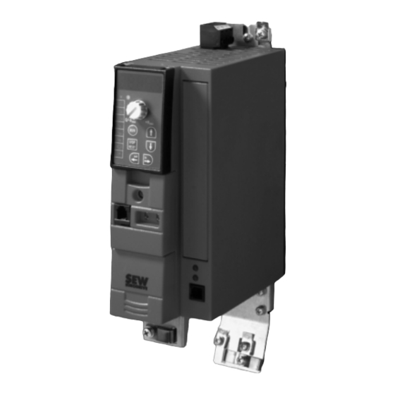
Page 8: Unit Design
Unit design Sizes 0XS / 0S / 0L Unit design Sizes 0XS / 0S / 0L [11] [12] [13] [10] Fixing strap X1: Power supply connection: 3-phase: L1 / L2 / L3 1-phase: L / N Status LED (visible without optional keypad) Optional keypad Connection for optional communication / analog module X10: Analog input... -
Page 9: Sizes 2S / 2
Unit design Sizes 2S / 2 Sizes 2S / 2 X1: Mains connection 3-phase: L1 / L2 / L3 / PE screw Status LED (visible without optional keypad) Optional keypad Connection for optional communication / analog module Option card slot Switch S11 for V-mA toggle analog input X10: Analog input X12: Binary inputs... -
Page 10: Size 3
Unit design Size 3 Size 3 X2: PE connection X1: Mains connection 3-phase: L1 (1) / L2 (2) / L3 (3) X4: DC link circuit connection (not used) X2: PE connection X2: Motor connection U (4) / V (5) / W (6) X3: Braking resistor connection R+ (8) / R–... -
Page 11: Size 4
Unit design Size 4 Size 4 X2: PE connection X1: Mains connection 3-phase: L1 (1) / L2 (2) / L3 (3) X4: DC link circuit connection (not used) X2: PE connection X2: Motor connection U (4) / V (5) / W (6) X3: Braking resistor connection R+ (8) / R–... -
Page 12: Unit Designation
Unit design Unit designation Unit designation MC 07 B 0004- 2 B 1- 4- 00 Design 00 = Standard Quadrants 4 = 4Q (with brake chopper) Connection type 3 = 3-phase / 1 = 1-phase 0 = No radio interference suppression Radio interference A = Radio interference... -
Page 13: Installation
Installation Installation notes Installation Installation notes Comply with the safety notes during installation. Tightening torques Basic unit power terminals: • Only use genuine connection elements. Note the permitted tightening torques of ® MOVITRAC B power terminals. – Size 0S / 0L: 0.5 Nm (4.4 lb.in) Line choke: •... - Page 14 Installation Installation notes Shielding and • Shield the control cables and use the shield clamps. earthing • Connect the shield by the shortest possible route and make sure it is earthed over a wide area at both ends. • You can ground one end of the shield via a suppression capacitor (220 nF / 50 V) to avoid ground loops.
-
Page 15: Deactivate The Emc Capacitors (Size 0 Only)
Installation Deactivate the EMC capacitors (size 0 only) ® Line filter MOVITRAC B frequency inverters have an integrated line filter as standard. They comply with the following limit value class to EN 55011 on the line side without further measures: •... - Page 16 Installation Deactivate the EMC capacitors (size 0 only) • Fasten screws to the unit [C]. • Close the unit. Deactivating the EMC capacitors stops earth-leakage currents from flowing over the EMC capacitors. • Please ensure that the earth-leakage currents are essentially only determined by the level of the DC link voltage, the PWM frequency, the applied motor line and its length and the motor used.
-
Page 17: Installation Of Cold Plate
Installation Installation of Cold Plate Installation of Cold Plate The dissipation of the frequency inverter power loss can take place via coolers that work with different cooling media (air, water, oil, etc.). A good thermal connection to the cooler is important for safe operation of the frequency inverters: •... -
Page 18: Wiring Diagram 230 V 0.37
Installation Wiring diagram 230 V 0.37 ... 2.2 kW / 400 V 0.55 ... 4.0 kW Wiring diagram 230 V 0.37 ... 2.2 kW / 400 V 0.55 ... 4.0 kW ® MOVITRAC Changeover REF1 FSC11B Reference potential for analog signals Higher-level controller H L ⊥... -
Page 19: Connection Braking Resistor Bw
Installation Connection braking resistor BW.. / BW..-T Connection braking resistor BW.. / BW..-T (X3:) (X3:) +R -R +R -R Has effect on K11 BW...-...-T 3-phase Has effect on K11 BW... When the internal thermostat triggers, K11 must be opened and DIØØ "Controller When the external bimetallic relay (F16) inhibit"... -
Page 20: Connecting The Brake Rectifier
Installation Connecting the brake rectifier Connecting the brake rectifier The connection of the brake rectifier requires a separate supply system cable; supply from the motor voltage is not permitted! Use contactors of utilization category AC-3 for K11 and K12 only. Always disconnect the brake in the DC and AC circuits in: •... -
Page 21: Startup
Startup General startup instructions Startup General startup instructions It is essential to comply with the safety notes during startup! 5.1.1 Prerequisite The drive must be configured correctly to ensure that startup is successful. ® MOVITRAC B frequency inverters are factory set to be taken into operation with the SEW motor adapted to the correct power level (4-pole, 50 Hz) in V/f control mode. - Page 22 Startup Starting the motor 5.3.2 Fixed setpoints The following travel cycle shows by way of example how the drive is started with the wiring of terminals X12:2...X12:6 and the internal fixed setpoints. "1" 12:2 = DIØ1 CW/Stop "0" "1" X12:3 = DIØ2 CCW/Stop "0"...
-
Page 23: Operation And Service
Operation and service Device information Operation and service Device information 6.1.1 Switch-off responses There are 3 switch-off responses depending on the error: Response Description Immediate stop This fault response causes immediate locking of the output stage with simultaneous control of the brake output so that an existing brake is applied. -
Page 24: List Of Errors (F-00
Operation and service List of errors (F-00 ... F-97) List of errors (F-00 ... F-97) Designation Response Possible cause Measure No error Over-current Immediate • Short circuit output • Rectify the short circuit switch-off • Output switching • Switching with inhibited output with inhibit stage only •... - Page 25 Operation and service List of errors (F-00 ... F-97) Designation Response Possible cause Measure System error Immediate Malfunction of inverter electronics, Check grounding and shielding and switch-off possibly due to EMC influence improve, if necessary. Contact SEW with inhibit Service for advice if this reoccurs. EEPROM Stop with Error when accessing EEPROM...
- Page 26 Operation and service List of errors (F-00 ... F-97) Designation Response Possible cause Measure Start condition Immediate Only in "VFC hoist" operating • Check connection between inverter switch-off mode: and motor with inhibit The motor could not be supplied with •...
-
Page 27: Status Displays
Operation and service Status displays Status displays 6.3.1 LED flash codes The LED on the front of the unit signals the following states: Status Display Color Flash code (optional with FBG) "ENABLE" Speed Green Constant light "ENABLE" at current limit Speed Green Rapid flashing... -
Page 28: Long Term Storage
Operation and service Long term storage 6.4.2 Repair service Please contact the SEW Electronics Service if you can not rectify a fault. Please always specify the unit status code number when you contact the SEW elec- tronics service so that our service personnel can assist you more effectively. Please provide the following information when sending the unit in for repair: Serial number (Æ... -
Page 29: Technical Data
Technical data CE marking, UL approval and C-Tick Technical data CE marking, UL approval and C-Tick 7.1.1 CE marking ® Low voltage MOVITRAC B frequency inverters comply with the regulations of the Low Voltage directive Directive 73/23/EEC and have the CE mark on the nameplate to this effect. ®... -
Page 30: General Technical Data
Technical data General technical data General technical data ® The following technical data applies to all MOVITRAC B frequency inverters, irrespec- tive of size and power: ® MOVITRAC All sizes Interference immunity Fulfills EN 61800-3 Interference emission with According to limit value class EMC compliant installation •... -
Page 31: Movitrac® B Electronics Data
Technical data MOVITRAC® B electronics data ® MOVITRAC B electronics data Function Terminal Designa- Default Data tion Setpoint input X10:1 REF1 0 ... +10 V (R > 200 kÊ) (differential input) X10:2 AI11 (+) 0 ... 20 mA / 4 ... 20 mA (R = 250 Ê) X10:3 AI12 (0) -
Page 32: Movitrac® B Technical Data
Technical data MOVITRAC® B technical data ® MOVITRAC B technical data ® 7.4.1 MOVITRAC B overview 230 V / 1-phase power supply connection Size Power 1.1 / 1.5 0.25 / 0.4 0.55 / 0.75 [kW / HP] 1.5 / 2.0 0.37 / 0.5 0.75 / 1.0 2.2 / 3.0... - Page 33 Technical data MOVITRAC® B technical data 7.4.2 AC 230 V / 1-phase / size 0XS / 0.25 ... 0.37 kW / 0.4... 0.5 HP 163.5 54.5 49.5 159.5 ® MOVITRAC MC07B (1-phase supply system) 0003-2B1-4-00 0004-2B1-4-00 Part number 828 491 1 828 493 8 INPUT Permitted rated supply voltage...
- Page 34 Technical data MOVITRAC® B technical data 7.4.3 AC 230 V / 1-phase / size 0S / 0.55 ... 0.75 kW / 0.75 ... 1.0 HP 163.5 159.5 ® MOVITRAC MC07B (1-phase supply system) 0005-2B1-4-00 0008-2B1-4-00 Part number 828 494 6 828 495 4 INPUT Permitted rated supply voltage...
- Page 35 Technical data MOVITRAC® B technical data 7.4.4 AC 230 V / 1-phase / size 0L / 1.1 ... 2.2 kW / 1.5 .. 3.0 HP 163.5 159.5 ® MOVITRAC MC07B (1-phase supply system) 0011-2B1-4-00 0015-2B1-4-00 0022-2B1-4-00 Part number 828 496 2 828 497 0 828 498 9 INPUT...
- Page 36 Technical data MOVITRAC® B technical data 7.4.5 AC 400 / 500 V / 3-phase / size 0XS / 0.25 ... 0.37 kW / 0.4... 0.5 HP 163.5 54.5 49.5 159.5 ® MOVITRAC MC07BB (3-phase supply system) 0003-5A3-4-00 0004-5A3-4-00 Part number 828 515 2 828 516 0 INPUT...
- Page 37 Technical data MOVITRAC® B technical data 7.4.6 AC 400 / 500 V / 3-phase / size 0S / 0.55 ... 1.5 kW / 0.75... 2.0 HP 163.5 159.5 ® MOVITRAC MC07B (3-phase supply system) 0005-5A3- 0008-5A3- 0011-5A3- 0015-5A3- 4-00 4-00 4-00 4-00 Part number...
- Page 38 Technical data MOVITRAC® B technical data 7.4.7 AC 400/500 V / 3-phase / size 0L / 2.2 ... 4.0 kW / 3.0... 5.0 HP 163.5 159.5 ® MOVITRAC MC07B (3-phase supply system) 0022-5A3-4-00 0030-5A3-4-00 0040-5A3-4-00 Part number 828 521 7 828 522 5 828 523 3 INPUT...
- Page 39 Technical data MOVITRAC® B technical data 7.4.8 AC 400/500 V / 3-phase / size 2S / 5.5 ... 7.5 kW / 7.5 ... 10 HP ® MOVITRAC MV07B (3-phase supply system) 0055-5A3-4-00 0075-5A3-4-00 Part number 828 524 1 828 526 8 INPUT Permitted rated supply voltage 3 ×...
- Page 40 Technical data MOVITRAC® B technical data 7.4.9 AC 400/500 V / 3-phase / size 2 / 11 kW / 15 HP ® MOVITRAC MC07B (3-phase supply system) 0110-5A3-4-00 Part number 828 527 6 INPUT Permitted rated supply voltage 3 × AC 400 V = AC 380 V –...
- Page 41 Technical data MOVITRAC® B technical data 7.4.10 AC 400/500 V / 3-phase / size 3 / 15... 30 kW / 20... 40 HP ® MOVITRAC MC07B (3-phase supply system) 0150-503-4-00 0220-503-4-00 0300-503-4-00 Part number 828 528 4 828 529 2 828 530 6 INPUT Permitted rated supply voltage...
- Page 42 Technical data MOVITRAC® B technical data 7.4.11 AC 400/500 V / 3-phase / size 4 / 37... 45 kW / 50... 60 HP ® MOVITRAC MC07B (3-phase supply system) 0370-503-4-00 0450-503-4-00 Part number 828 531 4 828 532 2 INPUT Permitted rated supply voltage 3 ×...
-
Page 43: Index
Index Index Immediate stop ..........23 Analog setpoints ..........21 Input contactor ........... 13 Auxiliary supply output ........31 Input fuse ............13 Installation altitude ..........30 Binary inputs ............31 Installation notes ..........13 Binary output ............31 Installation, line choke ........13 Brake rectifier, connection ........20 Interference emission ........ - Page 44 Index Technical data BG0L AC 230 V ......35 UL approval ............29 Technical data BG0L UL compliant installation ........17 AC 400 / 500 V ......38 Technical data BG0S AC 230 V ....33 Unit design ............8 Technical data BG0S AC 400 / 500 V ..36 Unit designation ..........
- Page 47 Startup: Brief description Startup: Brief description ® The frequency inverter MOVITRAC B can be connected directly to a motor of the same power. For example: A 1.5 kW motor can be connected directly to a MC07B0015. Procedure 1. Connect motor ®...
- Page 48 Gearmotors \ Industrial Gear Units \ Drive Electronics \ Drive Automation \ Services How we’re driving the world With people who With comprehensive With uncompromising think fast and With a worldwide With drives and controls knowledge in virtually quality that reduces the develop the service network that is that automatically...
Need help?
Do you have a question about the MOVITRAC B and is the answer not in the manual?
Questions and answers