Table of Contents
Advertisement
Quick Links
Advertisement
Table of Contents

Related Manuals for caron 6105


Summary of Contents for caron 6105
- Page 2 At CARON, we are committed to continuous quality improvement. Our goal is to supply our customers with highly reliable equipment at a fair price. In order to openly monitor our performance, we would appreciate your feedback on our products and services.
- Page 3 Revision Log Version Date Description 08-02-17 Updated consistency between all manuals 11-15-17 Added door heat and light connection instructions 07-16-18 Updated PM Kit info Model 6105 Operations ManualH Rev M 07-16-182/14/2021 Page 3 of 34...
- Page 4 Parts and labor for a period of one (1) year from date of shipment. Any part found defective will be either repaired or replaced at CARON's discretion, free of charge, by CARON in Marietta, OH. Parts that are replaced will become the property of CARON.
- Page 5 This warranty cannot be altered unless CARON agrees to an alteration in writing and expressly stated herein shall be recognized to vary or modify this contract.
-
Page 6: Table Of Contents
MAINTENANCE ................318 Routine maintenance .............. 318 Brief Troubleshooting .............. 519 Spare Replacement Parts ............. 6 Electrical Schematic 27………………………………………...21 Spare Replacement Parts ............29 Declaration of Conformity ..............30 Model 6105 Operations ManualH Rev M 07-16-182/14/2021 Page 6 of 34... -
Page 7: Introduction
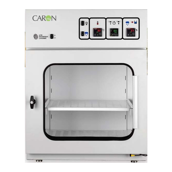
INTRODUCTION CARON’s 6105 fingerprint chambers are designed specifically to create conditions for developing DFO, Ninhydrin, and other fingerprint development process prints. The chamber features rapid condition recovery after the chamber door is opened and closed. The large viewing area offers easy observation of critical samples. The chamber interior is made of high quality, corrosion resistant material. - Page 8 Warning of dangerous electric voltage Earth (ground) protective conductor WARNINGS Local government may require proper lamp disposal Use eye protection, gloves and aprons if exposure to hazardous materials could occur Model 6105 Operations ManualH Rev M 07-16-182/14/2021 Page 8 of 34...
-
Page 9: Installation
Carefully remove all packing material. Please examine the chamber completely. Should any damage be found, notify the delivering carrier immediately. Report any shortages to your local distributor or contact CARON customer service at 740-373- 6809, 800-648-3042 (USA only) or www.caronproducts.com. -
Page 10: Power Requirements
The power cord of this chamber is equipped with a grounded plug. Be sure to connect the ground. CARON recommends that the chamber have a dedicated wall outlet. Verify correct power supply required for particular unit. (Nema 6-15 15A Cord, Model 6105-2 only.) - Page 11 The Condensate Recirculating System can be used in conjunction with CARON’s 6105 chambers as a water delivery system. This system is typically used in facilities where a drain or in-house source of distilled, RO or deionized water is not available.
-
Page 12: Operation
‘power on’ indicator light, temperature and timer displays will illuminate. Air should be gently circulating internally. ‘Power On’ Temperature indicator light and timer displays Power switch Control panel layout Light switch Humidity control enable Humidity Temperature Countdown controller controller timer Model 6105 Operations ManualH Rev M 07-16-182/14/2021 Page 12 of 34... - Page 13 Model 6105 Operations ManualH Rev M 07-16-182/14/2021 Page 13 of 34...
-
Page 14: Temperature Set Point
The Advance and Infinity/Home buttons are for diagnostics purposes. Pressing the Advance button will display the amount of time (in percent) that the heaters are on. Press the Infinity/Home button to return to the temperature display. Model 6105 Operations ManualH Rev M 07-16-182/14/2021 Page 14 of 34... - Page 15 Model 6105 Operations ManualH Rev M 07-16-182/14/2021 Page 15 of 34...
-
Page 16: Countdown Timer
4. Press the reset button; the time remaining resets to the total countdown time Press the reset button at any time to stop the countdown. 3 seconds after timer reaches Timer just reached 0:00, alarm is off 0:00, alarm is buzzing Model 6105 Operations ManualH Rev M 07-16-182/14/2021 Page 16 of 34... -
Page 17: Low Water Level Alarm
Once an adequate water supply is connected and the steam generator fills, the alarm light will automatically reset. If the low water level alarm light is on, the chamber will not control humidity. Model 6105 Operations ManualH Rev M 07-16-182/14/2021 Page 17 of 34... - Page 18 Model 6105 Operations ManualH Rev M 07-16-182/14/2021 Page 18 of 34...
- Page 19 The Advance and Infinity/Home buttons are for diagnostics purposes. Pressing the Advance button will display the amount of time (in percent) that the heaters are on. Press the Infinity/Home button to return to the temperature display. Model 6105 Operations ManualH Rev M 07-16-182/14/2021 Page 19 of 34...
-
Page 20: Viewing Light
Viewing light To illuminate the interior, turn on the light switch. If lighting does not come on, see troubleshooting guide. Light switch Model 6105 Operations ManualH Rev M 07-16-182/14/2021 Page 20 of 34... - Page 21 Model 6105 Operations ManualH Rev M 07-16-182/14/2021 Page 21 of 34...
-
Page 22: Calibration
Hit the ‘infinity’ key to save the setting and the main screen will be displayed. Allow the chamber to stabilize and repeat as necessary until the readings are within acceptable range. Record final readings below. Model 6105 Operations ManualH Rev M 07-16-182/14/2021 Page 22 of 34... - Page 23 Repeat Step 2 to return to P4 of the Programming Page. Use the ‘up’ and ‘down’ keys to return the setting from CAL to NONE. Press the ‘infinity’ key once to save the setting and return to the main screen. Model 6105 Operations ManualH Rev M 07-16-182/14/2021 Page 23 of 34...
- Page 24 Model 6105 Operations ManualH Rev M 07-16-182/14/2021 Page 24 of 34...
- Page 25 Model 6105 Operations ManualH Rev M 07-16-182/14/2021 Page 25 of 34...
-
Page 26: Maintenance
*Caron recommends using NIST traceable device to calibrate the controllers. A Vaisala HMI41/HMP46 temperature/humidity detector or a similar device is recommended. A “wick” type sensor is not recommended due to the likelihood that the sensor will become saturated and give inaccurate readings. - Page 27 Model 6105 Operations ManualH Rev M 07-16-182/14/2021 Page 27 of 34...
- Page 28 Here is a list of PM Kits that are available for models and accessories covered in this manual. Model PM Kit 6105-2 PM-BOTL101 6105-3 PM-BOTL101 Model 6105 Operations ManualH Rev M 07-16-182/14/2021 Page 28 of 34...
-
Page 29: Brief Troubleshooting
Temperature displayed is different than measured temperature inside chamber Can air flow freely throughout the chamber? Contact CARON service department to apply a temperature offset Temperature is higher than set point Is the set point within the unit specification range? ... - Page 30 Is the connector on the bottom of the door switch connected (see picture)? Is the door sealed tightly? Is the door gasket collapsed? Has the unit stabilized 1 hour? Model 6105 Operations ManualH Rev M 07-16-182/14/2021 Page 30 of 34...
- Page 31 Electrical Schematic Model 6105 Operations ManualH Rev M 07-16-182/14/2021 Page 31 of 34...
- Page 32 Model 6105 Operations ManualH Rev M 07-16-182/14/2021 Page 32 of 34...
-
Page 33: Spare Replacement Parts
RH SENSOR SOL-133 HUMIDIFICATION SOLENOLD SOL-135 DRAIN SOLENOLD LEV-106 STEAM GENERATOR LEVEL SWITCH HTR-144 STEAM GENERATOR HEATER REL-103 HUMIDITY SOLID STATE RELAY CTR-124 TEMPERATURE LIMIT CONTROLLER REL-150 TIME DELAY RELAY Model 6105 Operations ManualH Rev M 07-16-182/14/2021 Page 33 of 34... -
Page 34: Declaration Of Conformity
Conducted Disturbances Induced by RF Fields EN 61000-4-11:1994 Voltage Variations, Dips and Interruptions CISPR 11:1990 Emissions Standards 73/23/EEC Low-Voltage Directive EN 61010-1:2001 Safety requirements for electrical equipment for measurement, control, and laboratory use. Model 6105 Operations ManualH Rev M 07-16-182/14/2021 Page 34 of 34...
Need help?
Do you have a question about the 6105 and is the answer not in the manual?
Questions and answers