Table of Contents
Advertisement
Advertisement
Table of Contents

Related Manuals for BAFANG DP C01.RS 232.7


Summary of Contents for BAFANG DP C01.RS 232.7
- Page 1 Max Drive System User Manual...
- Page 2 Suzhou Bafang Electric Motor Science-Technology Co., Ltd. www.szbaf.com...
-
Page 3: Table Of Contents
CONTENTS MPORTANT OTICE ........................... 6 OR YOUR AFETY ............................7 DRIVE UNIT DVANTAGES ............................9 COPE OF PPLICATION ......................... 9 AMING ............................9 ECHNICAL ARAMETERS ......................11 RIVE TRUCTURE AND IMENSIONS ..................12 SYSTEM INSTALLATION ........................14 IST OF OOLS TO BE ........................ - Page 4 INK THE AILLIGHT TO THE RIVE ................... 33 INK THE ENSOR TO THE RIVE ..................34 INSTALLATION OF THE FRONT CHAINWHEEL AND THE CHAIN COVER ....... 35 ) ........... 35 NSTALLATION OF THE HAINWHEEL WITHOUT A CHAIN COVER ) ..................37 HAIN OVER NSTALLATION...
- Page 5 ): ..................56 AINTENANCE ARNING INACTIVE BY DEFAULT : ........................57 TEMS FOR ECONDARY ETTING : ............................57 ASSWORD NPUT : ............................58 PEED IMIT HANGE : ..........................59 ATTERY OMMUNICATION RROR EFINITIONS ........................60 FAULT ALERT INTERFACE7. LIST OF MATERIALS ................62 AFTER-SALES AND WARRANTY POLICY ..................
-
Page 6: Important Notice
Important Notice The Dealer Manual is to be used by professional e-bike mechanics. Users who have not received training on electric bicycle assembly shall not attempt to assemble parts and components even with the Dealer Manual. If you doubt about any part of the manual, do not install the product. ... -
Page 7: For Your Safety
When installing this product, be sure to follow the instructions given in the user's manual. It is recommended that you use only genuine Bafang parts at these times. The bicycle may suddenly fall over and serious injury may result if bolts and nuts are left loosened, or the product is damaged or improperly adjusted. - Page 8 The frequency of maintenance will vary depending on the riding conditions. Periodically clean the chain using an appropriate chain cleaner. Do not use alkaline or acidic cleaning agents to remove rust under any circumstances. If such cleaning agents are used, they may damage the chain and serious injury may result.
-
Page 9: Drive Unit
Natural wear and tear due to normal use and aging is not within our scope of quality guarantee. Please contact the seller for software updates (if any). The newest information on software will be available on the home page of Bafang website: www.szbaf.com 1. Drive Unit 1.1 Advantages... - Page 10 Naming Rule: The nameplate is engraved on the shell, showing such information as follows: MM G33.350 36V 250W 1511070036 (1) MM G33.250─ Name of the drive unit; (2) 36V─ Rated motor voltage; (3) 250W─ Rated motor power; (4) 151107─ Date of production, November 7, 2015 in this example; 0036─...
-
Page 11: Main Technical Parameters
1.4 Main Technical Parameters Classification Freewheel version Coaster brake version Rated voltage (DCV) Rated power(W) Rated efficiency (%) ≥80% Max current 18A for the coaster brake version and 14A for the freewheel version Rated rotating speed(rpm) 100±5 Maximum torque(N.m) ≥80 Chain wheel 36T, 38T Optional chain cover... -
Page 12: Drive Unit Structure And Dimensions
1.5 Drive Unit Structure and Dimensions... -
Page 14: System Installation
System Installation 2.1 List of Tools to be Used Compone Use of the Tools Tools Internal hexagonal Display To fix the screw M4 wrench To fix and remove the Socket spanner chain wheel locknut To fasten M4 screws which are used to fix the Cross screwdriver chain cover binder plate... -
Page 15: Component Names
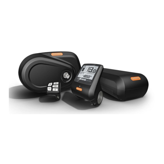
2.2 Component Names A. Drive unit B. Front chain wheel C. External RPM- detecting sensor D. Battery E. Auxiliary keypad F. Display Display Installation ( DP C01.RS232.7... - Page 16 A. a rubber clamping ring (whose inner diameter is Φ22.2 or Φ25.4) Left and right display clamps for theΦ22.2 handlebar: Left clamp - 2316020400017 One or two rubber clamping rings may be needed depending on the Right clamp - 2316020400018 diameter of the handlebar (the applicable handlebar specifications are Φ22.2, Φ25.4 and Φ31.8).
-
Page 17: Auxiliary Keypad Installation
hexagonal wrench to fasten the left and right clamps onto the handlebar. Tool: Adjust the angle of the display so that the user can easily see the display screen when riding. When the angle has been adjusted, tighten the screws to the specified torque. Tightening torque: 1N.m 2.4 Auxiliary Keypad Installation... - Page 18 A. keypad clamp Open the auxiliary keypad and assemble it onto a position that is easy for operation. Adjust the angle of the auxiliary keypad to ensure that the keypad is easy to see during riding. (Applicable to the handlebar whose external diameter is Φ22.2mm) B.
-
Page 19: External Rpm-Detecting Sensor Installation
H. female connector at the display h. male connector at the EB-BUS Match the female connector at the display with the male connector at the EB-BUS as shown in the picture above. 2.5 External RPM-detecting Sensor Installation A. external RPM- detecting sensor B. - Page 20 A. dust cap (2301030000003 ) B. mounting bolt M5*12 C. external RPM- detecting sensor D. sensor bracket (chain stay boss) Tool: If the gap is within the specified range, use the mounting bolt to fix the speed sensor. If the gap is over 25mm, please put spacers between the sensor and the chain stay boss to reduce this gap.
- Page 21 Magnetic mounting (PS01010701/2327000000 003) Tighten up the magnetic mounting nut with a straight Tool: screwdriver. Tightening torque: 1.5 - 2 N·m Arrange the speed sensor and the magnetic steel as shown in the picture above. After installing the magnetic steel, please make sure its center faces the center of the speed sensor’s induction zone.
-
Page 22: Drive Unit Installation
2.6 Drive Unit Installation A. battery cable B. taillight cable C. external RPM- detecting sensor cable D. headlight cable E.EB-BUS Cables should be arranged in advance according to the bicycle type and the cabling system before installing the drive unit. A. - Page 23 C.M6 nuts (1401080000101) Insert, from the right, special M6 nuts into the mounting holes in the bicycle frame and the drive unit. D.M6 bolts (1401080000099) Insert, from the left, the M6 bolts into the bicycle frame so that Tool: they will come to contact with the nuts. Tighten bolts onto nuts with a specified torque.
- Page 24 A. upper cover of the cabling B. the cabling box body Open the terminal box and get ready to link female connectors with male connectors. Push the lower part of each of the male buckles on the cabling box body (in the direction as show by the arrows in the picture above) to release the female buckles on the upper cover.
- Page 25 C. cabling layout (2307070000001 D. cable clips (1401300000001 Open the cabling box, link all cables to the drive unit and put all connectors in the cabling box according to the cabling diagram printed on the upper cover of the cabling box (see C in the picture above). After matching all male connectors with female connectors, cover the cabling box with the upper cover and thread the cables through cable clips (D in the picture above) following the principle of "upper thin...
- Page 26 The picture above shows how the drive unit looks like when the cables are re-arranged with the help of the two cable clips. Please be noted that all cables must thread through the cable clips after going out of the cabling box. A.
- Page 27 C. screw holes on the drive unit’s cover D. end cover on the right E. cable gatherers 1401150100005 F. cross head screw assembly M3*8 (1401020000127) Figure 1 Figure 2 Tool: Make sure that the cover's bottom is fastened onto the drive unit's bottom with screws after the cover's upper part buckles into the slot (see Figure 1).
- Page 28 Tightening torque:1N.m...
- Page 29 Figure 3 Figure 4 Figures above show what the drive unit looks like when the drive unit cover has been fixed onto it. Brake cables and gear-shift cables can either be arranged in the channel at the bottom of the drive unit (see Figure 3 where cable gatherers are provided) or within the inner space of the frame adapter (see Figure 4 where no cable gatherers are provided).
-
Page 30: System Cabling
System Cabling 3.1 Link the Battery Cable to the Drive Unit A. female connector communication cables at the battery a. male connector communication cables at the drive unit B. female connector The power bus, which is made up of a positive battery cable, a positive cable at the battery negative battery cable, battery communication cables, is linked to... -
Page 31: Link The External Rpm- Detecting Sensor To The Drive Unit
negative cable at the drive unit 3.2 Link the External RPM-detecting Sensor to the Drive Unit... -
Page 32: Link The Eb-Bus To The Drive Unit
I. female connector external RPM-detecting sensor cable i. male connector at sensor extension cable E. male connector at the RPM sensor extension cable e. female connector First link the female connector at the external RPM-detecting for the RPM sensor sensor to the male connector at the RPM sensor extension cable. at the drive unit Then link the male connector at the RPM extension cable to the female connector for the RPM sensor at the drive unit. -
Page 33: Link The Headlight Cable To The Drive Unit
3.4 Link the Headlight Cable to the Drive Unit F. female connector headlight cable f. male connector for the headlight at the drive unit Link the headlight cable to the connector for the headlight at the drive unit. 3.5 Link the Taillight to the Drive Unit G. -
Page 34: Link The Gear Sensor To The Drive Unit
unit. 3.6 Link the Gear Sensor to the Drive Unit j. female connector at the gear sensor extension cable H. female connector at the gear sensor extension cable h. male connector for the gear sensor at the drive unit First link the male connector at the gear sensor to the female connector at the gear sensor extension cable. -
Page 35: Installation Of The Front Chainwheel And The Chain Cover
female connector at the gear sensor extension cable to the male connector for the gear sensor at the drive unit. Installation of the Front Chainwheel and the Chain Cover 4.1 Installation of the Chainwheel (without a chain cover) - Page 36 A. chain wheel Thread the spline shaft through the chain wheel holder with spline teeth engaged with spline holes. B. locknut 1334000000001 A. chainwheel A special locknut will be used to position the chainwheel in the right place. Tightening torque:35N.m Tool: Suggestion: A 36T or 38T chain wheel is recommended.
-
Page 37: Chain Cover Installation (Optional)
Chain Line: 45mm integratable chain wheel Preferably 36-38T guard (1325020000002) Applicable to a city bike which equipped with an internal gearshift system but not a full chain cover. Chain Line: 49mm integratable chain wheel Preferably 36-38T guard (1325020000001) Applicable to a city or mountain bike with external... - Page 38 A chain cover bracket and screws are necessary in order to mount the drive unit onto a bike with a full chain cover. full chain cover B. bracket for the full chain cover (140115010000 cross recessed head screw M4 (140102000011 Open the full chain cover and adjust it by following the instruction book.
- Page 39 chain wheel bushing block E. chain wheel 1325020000001 Install the chain wheel following the installation method. Chain Line: 48mm...
- Page 40 Preferably 36-38T Applicable to a city bike which is equipped with an internal gearshift system and a full chain cover. Refer to the chain cover instruction book and install the chain cover after the chain wheel has been installed. Note: Not all full chain covers are applicable to the Max drive unit. A right full-chain ...
- Page 41 A. p-shaped chain cover holder (1401220200003) B. cross recessed pan head screw M4 (1401020000111) Assemble the p-shaped chain cover bracket onto the drive unit and fasten them together with screws. Tightening torque:2N.m Tool: C. CL-45mm chain wheel assembly (1325020000001) Install the chain wheel onto the appropriate position by following the chain wheel installation method.
- Page 42 Applicable to a city bike with an internal gearshift system and a p-shaped chain cover. D. locknut 1334000000001 Install the chain wheel onto the spline shaft. Tool: cross recessed head screw M5...
- Page 43 The figure above shows how a p-shaped chain cover is mounted onto the drive unit with screws. The figure above shows a bike frame, onto which both the p-shaped chain cover and the drive unit are mouned. Note: Not all p-shaped chain covers match the Max drive unit. Please choose a right ...
-
Page 44: Crank Installation
4.3 Crank Installation Installation of cranks onto a bottom bracket where a chain cover is also mounted. A. cranks right straight crank with a cap (1327040000001) left straight crank (1327020000001) crank mounting screw M8 (1401020000109 ) Note: The crank on the right varies as the chain cover varies. - Page 45 Installation of cranks onto a bottom bracket where no chain cover is mounted A. right straight crank (1327010000001 ) left straight crank (1327020000001) crank mounting screw (1401020000109 ) Tool: Fasten the right crank onto the bottom bracket on the right with a socket head cap screw M8.
-
Page 46: Display
Display 5.1 Specifications and Parameters of the Display 36V Power Supply; Rated Current: 10mA Maximum Operating Current: 30mA Power-off Leakage Current: <1uA Operating Current Supplied to the Controller: 50mA Operation Temperature: -18 ~ 60 ℃ ... -
Page 47: Function Overview And Key Definitions
5.3 Function Overview and Key Definitions Function Overview The display adopts a two-way serial communication protocol. The external five-key keypad enables users to operate the display conveniently. Speed display: displaying the real-time speed SPEED, the max speed MAXS and the average speed AVG. -
Page 48: Items To Be Shown On The Display
charge/discharge cycles and riding distance. The display automatically estimates the battery life, and gives battery maintenance warnings when the number of charge/discharge cycles exceeds the set value. When the accumulated riding distance exceeds the set value, the display will also prompt bicycle maintenance necessity. -
Page 49: Key Definitions
battery charge/discharge cycles exceeds the set value) Mode indication: it displays the current PAS level (Level 1 to Level 5); if there is no numeric display, it means that there is no assistance. If the rider is walking and pushing his/her bicycle, only the symbol will be displayed. -
Page 50: Distance Mode And Speed Mode Switch
In the manual gearshift mode, press the "up" or "down" key to switch the PAS level to change the motor assist power. The lowest PAS level is Level 1 and the highest level is Level 5. When the display is on, the default PAS level is Level 1. It indicates no power assist when there is no numeric PAS level display. -
Page 51: Headlight/ Backlight Switch
Mode Switch Interface Headlight/ Backlight Switch After pressing and holding the "headlight" key for 2 seconds, both the taillight and the display backlight (needing the support from the controller) will be turned on. Press and hold the headlight again for 2 seconds to power off the headlight and the display backlight (If the display is turned on in a dark environment, the backlight/ headlight will be automatically turned on. -
Page 52: Battery Level Indication
Walk Assistance Mode Switch Interface Battery Level Indication When the battery voltage is normal, the battery is indicated by a certain number of segments with the border lighted according to the actual quantity of electricity. It the battery is under-voltage, all of the 10 segments will black out with the border blinking, indicating that the battery needs to be charged immediately. -
Page 53: Parameter Setting
5.5 Parameter Setting Items to be Set: Backlight Data reset km/mile Light sensitivity Automatic off time brightness Wheel Input of the Change of Maintenance diameter password speed limit warning settings selection Setting Preparation When the display is active, pressing the “mode” key two times (the interval between the two pressing actions should be shorter than 0.3 seconds), the system will enter the MENU parameter setting state, in which the display parameters can be set. -
Page 54: Data Reset
In the parameter setting state, when the parameter to be set begins to flash, press the "up" or "down" key to adjust the parameter value. Press the "mode" key to switch among the to-be-set parameters. Press the "mode" key two times (the interval between the two pressing actions should be shorter than 0.3 seconds) to exit parameter setting state. -
Page 55: Km/ Mile
Km/ mile: When the speed field displays S7, press the “up” or “down” key to switch between km/h and mile/h or km and mile. After this setting, press the "mode" key for shorter than 0.3 seconds to enter the light sensitivity setting interface. Light Sensitivity: speed... -
Page 56: Automatic Off Time
After this setting, press the "mode" key for shorter than 0.3 seconds to enter the setting interface of automatic off time. Automatic Off Time: When the speed field displays OFF, press the “up” or “down” key to display a figure between 1 and 9. This figure indicates the minute that it takes to automatically shut down the display. -
Page 57: Items For Secondary Setting
Maintenance Warning Interface The display will prompt maintenance necessity based on such information as the accumulated riding distance and the battery charge/discharge cycles. When the accumulated riding distance exceeds 5,000 km (can be customized by the bicycle manufacturer) , there will prompt, on the display, the symbol the sign of accumulated riding distance will flash for 4 seconds when the display is started up, indicating the bicycle needs maintenance. -
Page 58: Speed Limit Change
the default password is "0512". Press the “mode” key to confirm the setting. If the set password is wrong, the system automatically will return to the previous interface. If the set password is correct, the system will enter <wheel diameter selection>. Wheel Diameter Selection: When the field for speed displays Wd, press the “up”... -
Page 59: Battery Communication
Battery Communication: At this moment, the field for speed displays b01 and the field for distance displays the speed limit. Press the “mode” key for shorter than 0.3 seconds to set the other communication items in sequence. After all these settings, double press the “mode”... -
Page 60: Error Code Definitions
lowest temperature total voltage current average current remaining capacity full capacity relative state of charge absolute state of charge charge/discharge cycles the longest time that the battery was left uncharged after a charge in the past the time that the battery has been left uncharged since last charge 1st cell voltage 2nd cell voltage... - Page 61 “06”is displayed in the Low voltage protection Check the battery voltage. field for speed display. “07”is displayed in the Overvoltage protection Check the battery voltage. field for speed display. “08”is displayed in the Motor hall signal cable Check the motor module. field for speed display.
-
Page 62: Fault Alert Interface7. List Of Materials
Fault Alert Interface... - Page 63 7. List of Materials Model Material Quantit Unit Name Specification Dsiplay Unit left 2316020400 display Φ22.2 rubber clamping clamp Φ22.2 ring right 2316020400 (optional) display clamp DP C01.RS left Display 2316020400 232.7 display Φ25.4 rubber Accessor clamping clamp Φ25.4 ring right 2316020400 (optional)
- Page 64 1401080000 M6 nut 1401080000 M6 bolt 1333000000 Motor cover Motor Cover 1401150100 Cable gather Accessor cross head screw 1401020000 M3*8 assembly M3*8 1401150100 Full chain cover bracket Chain cover P-shaped chain cover 1401220200 Assembl bracket y Tools M4 cross recessed pan 1401020000 M4*8 head screw...
- Page 65 1327020000 Left straight crank 170mm 1401020000 Crank mounting screws Follow the EB-BUS order requirements. Follow the External RPM- order detecting sensor cable requirements. Follow the Cables Cables Battery cable order requirements. Follow the Headlight cable order requirements. Follow the Taillight cable order requirements.
-
Page 66: After-Sales And Warranty Policy
Suzhou Bafang Motor Science-Technology Co., Ltd (hereinafter referred to as the "Bafang Motor") guarantees: During the warranty period, customers enjoy warranty service from Bafang for products bought from Bafang as long as the products are within the warranty period and the issues are indeed quality issues concerning material and workmanship. - Page 67 Bafang will provide customers (dealers or bike manufacturers) with free spare parts so that they can correct the problem themselves; if it's a big issue, Bafang will provide customers with free spare parts, show them what to do by sending them videos or documents or on some special occasions repairing the products for them.
Need help?
Do you have a question about the DP C01.RS 232.7 and is the answer not in the manual?
Questions and answers