
Related Manuals for BAFANG H400


Summary of Contents for BAFANG H400
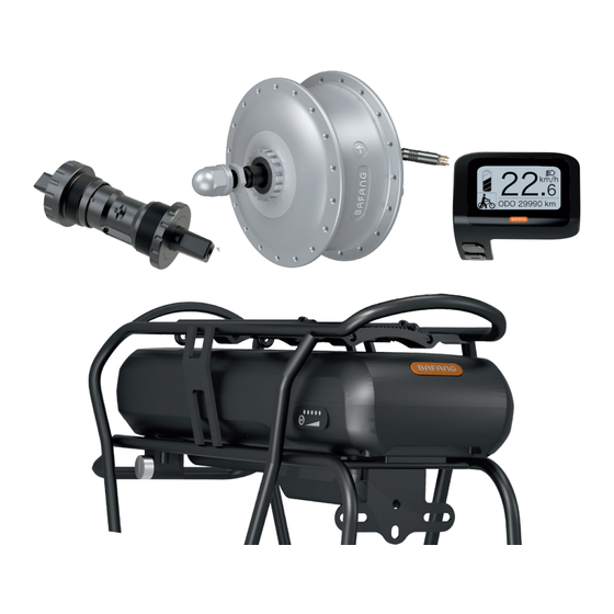
- Page 1 DEALER MANUAL H400 Drive System Original instruction manual Read carefully before use. Keep for later reference. BF-DM-S-H400-1-EN-PRINT, November 2019...
-
Page 2: Table Of Contents
SYMBOL INSTRUCTION If you see the following symbols there is always a Danger: This symbol indicates possible health and safety hazards that may arise, if certain possibility of danger. measures are not taken into consideration. The warning symbols are as follows: User Manual: Please read the manual before Note: This symbol indicates information about using the pedelec. -
Page 3: Guide
1 GUIDE 1.1 Quick start This section provides important information and instructions that will allow you to use your pedelec in a safe manner. First, please read the safety instructions to find out about the legal regulations that apply to you. Perform all safety checks in accordance Practice using the pedelec in a quiet and safe with the "Before each trip"... -
Page 4: Important Notice
2 IMPORTANT NOTICE 2.2 Pedelec modifications Be sure to follow the instructions in the manual when using this product. are prohibited • If you are lending your pedelec to third par- ties, please give them the instruction manual Do not change the pedelec drive system in any along with the pedelec. -
Page 5: Laws And Regulations
The authorized retailer can only use the original spare parts Before driving on public roads, please read the from Bafang for maintenance. applicable countries regulations carefully. The use of pedelecs on public roads must comply with Do not use no high-pressure water jet or local regulations. -
Page 6: Vehicle Transport
3 VEHICLE TRANSPORT Remove the battery during transport and store When transporting the pedelec by train, the relevant laws and regulations must be complied the battery in a safe and dry place. with. Before using public transport, please find Do not transport a battery without the correct out which means of transport are suitable for procedure. -
Page 7: Guaranty
5 GUARANTY All warranty and guarantee conditions are Warranty and warranty exclusions: subject to applicable laws and regulations from • Modification, manipulation or improper your brand. repair of the product. The condition for warranty and guarantee • Improper use of the product. claims is that the instructions for the system are •... - Page 8 6 DEALER MANUAL FOR H400 (FM G320.250.R) CONTENT 6.1 Introduction 6.3 Drive Unit Installation 6.2 Specifications 6.3.1 List of Tools to be used 6.2.1 Outline and geometric size 6.3.2 Motor Installation 6.4 Maintenance 6.2.2 Surface 6.2.3 Storage Information BF-DM-C-FM G320-R-EN November 2019...
-
Page 9: Introduction
6.1 INTRODUCTION • Scope Applies only to electrically powered pedelecs developed or licensed by Bafang. It is suitable for city and trekking bikes, which have been developed for road use. The engine is not suitable for sport competitions. • Identification... -
Page 10: Specifications
6.2 SPECIFICATIONS Motor model: FM G320.250.R Rated power (W) Rated voltage (V) 36 / 43 Waterproof IP65 Certification CE / ROHS / REACH Outdoor Temperatures -20℃~45℃ 6.2.1 Outline and geometric size OLD: 100mm Shaft length: 152mm Motor cable length: L=250mm 6.2.2 Surface Shockproof black and silver coating 6.2.3 Storage Information... -
Page 11: Drive Unit Installation
6.3 DRIVE UNIT INSTALLATION 6.3.1 List of Tools to be used Use of the Tools Tools To fasten M12*4 nut on the roller brake Open-end wrench To fasten M12 cap lock-nuts 6.3.2 Motor Installation First install the roller brake at the non- Mount one anti-rotation washer on both cable outlet side of the motor. -
Page 12: Maintenance
6.4 MAINTENANCE • Maintenance must be carried out by autho- rized personnel with the correct equipment. • Do not disassemble the motor. • Do not use thinners or other solvents to clean the components. Such substances can damage the surfaces. •... - Page 13 7 DEALER MANUAL FOR DP C11.CAN CONTENT 7.1 Important Notice 7.7.2 Selection of Support Levels 7.2 Introduction of Display 7.7.3 Selection mode 7.3 Product Description 7.7.4 Headlights / backlighting 7.7.5 Walk Assistance 7.3.1 Specifications 7.7.6 SERVICE 7.3.2 Functions Overview 7.4 Display Installation 7.7.7 Battery capacity indication 7.5 Display 7.8 Settings...
-
Page 14: Important Notice
7.1 IMPORTANT NOTICE • If the error information from the display • Please use this product with care. cannot be corrected according to the inst- • Do not use thinners or other solvents to ructions, please contact your retailer. clean the display. Such substances can •... -
Page 15: Product Description
7.3 PRODUCT DESCRIPTION 7.3.2 Functional Overview 7.3.1 Specifications • Speed display (including top speed and aver- • Operating temperature: -20℃~45℃ age speed, switching between km and miles) • Storage temperature: -20℃~50℃ • Battery capacity indicator • Waterproof: IP65 • Llighting control •... -
Page 16: Display Installation
7.4 DISPLAY INSTALLATION Remove the holding bracket from the Now connect the Display connector to the display, and then place the display into EB-Bus connector, ensuring both connec- position on the handlebar. (suitable for tors are kept parallel when pushing firmly ∮22.2mm handlebar). -
Page 17: Display
7.5 DISPLAY Display of battery capacity in real time. Support level The display shows this symbol , When the lights are turned on. Unit of speed Digital speed display Trip: Daily kilometers (TRIP) - Total kilometers (ODO) - Top speed (MAX) - Average speed (AVG) - Rremaining distance (RANGE) - Ener- gy Consumption (CALORIES) - Output power (POWER)- Travel time (TIME). -
Page 18: Normal Operation
7.7 NORMAL OPERATION 7.7.1 Switching the System ON/OFF Press and hold (>2S) on the display to turn on the system. Press and hold (>2S) again to turn off the system. If the "automatic shutdown time" is set to 5 minutes (it can be reset with the "Auto Off" function, See "Auto Off"), the display will automatically be turned off within the desired time when it is not in operation.If the password function is enabled, you must enter the correct password to use the system. -
Page 19: Headlights / Backlighting
7.7.4 Headlights / backlighting Hold the button (>2S) to activate the headlight and taillights. Hold the button (>2S) again to turn off the headlight. The brightness of the backlight can be set in the display settings "Brightness". 7.7.5 Walk Assistance The Walk assistance can only be activated with a standing pedelec. -
Page 20: Service
7.7.6 SERVICE The display shows "SERVICE" as soon as a certain number of kilometers or battery charges has been reached. With a mileage of more than 5000 km (or 100 charge cycles), the “SERVICE" function is displayed on the display. Every 5000 km the display "SERVICE" is displayed every time. This function can be set in the display settings. -
Page 21: Settings
7.8 SETTINGS After the display is turned on, press and hold the buttons (at the same time) to enter into the setting menu, By pressing the button (<0.5S), you can highlight and select Display Setting, Information or Exit. Then press the button (<0.5S) to confirm your selected option. - Page 22 7.8.1.2 "Unit" Selections in km/Miles Press the button (<0.5S) to highlight “Unit” in the Display setting menu, and then press button (<0.5S) to select. Then with the button choose between “Metric” (kilometer) or “Imperial” (Miles). Once you have chosen your desired selection, press the button (<0.5S) to save and exit to the "Display setting".
- Page 23 7.8.1.5 "Assist Mode" Set support level Press the button (<0.5S) to highlight “Max Pass” in the Display setting menu, and then press button (<0.5S) to select. Then with the button choose between “3/5/9” (the amount of support levels). Once you have chosen your desired selection, press the button (<0.5S) to save and exit to the "Display setting".
-
Page 24: Information
7.8.2 "Information" Once the display is turned on, press and hold the buttons (at the same time) to enter into the setting menu, press the button (<0.5S) to select “Information”, then press the button (<0.5S) to confirm and enter into "Information". 7.8.2.1 Wheel Size Press the button (<0.5S) to highlight “Wheel Size”, then press the... - Page 25 7.8.2.3 Battery Information Press the button (<0.5S) to highlight “Battery Info”, then press the button (<0.5S) to confirm. Now press the button (<0.5S) to view the contents. To return, press the button (<0.5S) to exit back to the "Information". Code Code definition unit Code...
-
Page 26: Display Information
7.8.2.5 Display Information Press the button (<0.5S) to highlight “Display Info”, then press the button (<0.5S) to confirm. Now press the button (<0.5S) to view Hardware Version or Software Version. To return, press the button (<0.5S) to exit back to the "Information". 7.8.2.6 Torque Information Press the button (<0.5S) to highlight “Torque Info”, then press the... -
Page 27: Error Code Definition
7.9 ERROR CODE DEFINITION The HMI can show the faults of Pedelec. When a fault is detected, one of the following error codes will be indicated too. Note: Please read carefully the description of the error code. When the error code appears, please first restart the system. - Page 28 Error Declaration Troubleshooting 1. Check all connectors from the battery are correctly connected to the motor. Error with the temperature sensor inside of the battery 2. If the problem still occurs, please change the Battery. 1. Allow the pedelec to cool down and restart the The protection temperature inside system.
- Page 29 Error Declaration Troubleshooting 1. Check that all connections are connected correctly. 2. Please connect the pedelec to the BESST system to see if speed signal can be read by the BESST tool. Speed signal of the torque sensor has an error 3.
- Page 30 Error Declaration Troubleshooting Using the BESST tool update the controller to see WDT circuit is faulty if this resolves the problem. If not, please change the motor. Total voltage from the battery is Please change the battery. too high Total voltage from the battery is Please Charge the battery.
- Page 31 8 DEALER MANUAL FOR BT C01.XXX.UC CONTENT 8.1 Introductions 8.2.1 Installing the battery 8.2.2 Charging the Battery 8.1.1 Battery 8.2.2.1 Safety Instructions 8.1.1.1 Safety Instructions 8.2.3 LED Display for Charge Status and Charging Capacity 7 8.1.1.2 Battery Storage 8.2.3.1 Sleep State 8.1.1.3 Battery Wear 8.3 Specifications 8.1.1.4 Pedelec Riding Distance...
-
Page 32: Battery
A faulty battery can lead to overheating, smoking or burning. When the battery gets hot keep yourself and Use only the original BAFANG charger to charge others a safe distance away from the battery. In the battery. The battery is not fully charged case of damage or heat you should avoid when it is delivered. -
Page 33: Battery Storage
Do not intentionally close the battery • To prevent a deep discharge, the battery is short. put into sleep mode after a certain time. Never touch the plus and minus contact. Do not • Do not extend the battery to temperatures allow the battery to encounter metal objects. -
Page 34: Charger
Disconnect the charger from the power supply when not in use. 8.1.2.1 Battery charger Instructions • Use only the original Bafang charger that came Read the instructions on the external label of with your pedelec. your charger before using the battery. -
Page 35: Operation
8.2 OPERATION 8.2.1 Installing the battery 8.2.2 Charging the battery If you decide to use a key lock, place the Use only the original battery charger supplied to lock under the battery rail, and tighten you, as there is a risk of fire or explosion if the with 2 X M5*10 screws. -
Page 36: Safety Instructions
When the battery is fully charged, the charging • Charge the battery only in a well-ventilated process stops automatically. Unplug the connec- room. tor from the battery and then removed from the • Do not cover the charger/battery during mains. charging. -
Page 37: Sleep State
8.2.3 LED display for charging status and charging capacity “ “ Press the button for 1 second to indicate the state of charge from the LEDs on the battery. “ “ Press the button for 6 seconds to indicate the capacity of the battery. 8.2.3.1 Sleep state To prevent the battery from being discharged, the battery management system puts the battery... -
Page 38: Specifications
8.3 SPECIFICATIONS 8.3.1 Battery Primary Settings BT C01.340.UC BT C01.450.UC BT C01.600.UC BT C01.750.UC Rated voltage 43 DCV 43 DCV 43 DCV 43 DCV Nominal Capacity 7.8 Ah 10.4 Ah 14 Ah 17.5 Ah 6.43 Ah 8.5 Ah 11.4 Ah 14.3 Ah Rate Capacity (1C Discharge) - Page 39 9 DEALER MANUAL FOR SR PA152/162.32.S CONTENT 9.1 Introduction of Display 9.2 Specifications 9.2.1 Outline and geometric size 9.2.2 Cautions 9.3 Sensor Installation 9.3.1 List of Tools to be used 9.3.2 Install Sensor 9.3.3 Remove Sensor BF-DM-C-SR PA152/162-EN November 2019...
-
Page 40: Specifications
9.1 INTRODUCTION OF SENSOR This is a speed sensor for the BB (bottom bracket). This high-quality and high-perfor- mance BB speed sensor is installed on electric bicycles or tricycles. The CPU processes the speed signals collected by the speed sensor by means of non-contact induction and analyzes the motor operating direction. -
Page 41: Outline And Geometric Size
9.2.1 Outline and geometric size X: (Shaft Length of SR PA152.32.S) : 126mm X: (Shaft Length of SR PA162.32.S) : 130mm Connector Length(mm), Connector type: 150 G6.5.4 / 950 G6.5.4 9.2.2 Cautions • The pedelec should be stored in a ventilated dry room. Avoid storing the pedelec near strong mag- netic objects. -
Page 42: Sensor Installation
9.3 SENSOR INSTALLATION 9.3.1 List of Tools to be used Use of the Tools Tools To fasten or remove lock cap on sensor Special tools 9.3.2 Install Sensor Assemble requirements: 3. Screw the left lock cap (A) clockwise from non-chain wheel side into the bottom •... - Page 43 5. Place sensor into the BB of frame and 8. Put onto the dust-proof plug (F) at both screw the lock cap (from chain wheel side) sides of the shaft. anticlockwise into the BB. 6. Screw the lock cap anticlockwise into the bottom bracket and fasten with special 9.
-
Page 44: Remove Sensor
9.3.3 Remove Sensor 1. Remove the rubber ring (G) 4. Screw Off anticlockwise the lock cap (A) on non chain wheel side with special tools (C). 2. Screw Off the lock cap (H) with special tools (C). 5. Finish the dismantlement. 3. - Page 45 7 DEALER MANUAL FOR CR S10F.350.FC CONTENT 7.1 Introduction 7.2 Product Description 7.2.1 Specifications 7.2.2 Outline and geometric size 7.2.3 Functions Overview 7.3 Controller Installation 7.3.1 Installing the controller 7.3.2 Cabling BF-DM-C-CR S10F-EN November 2019...
-
Page 46: Introduction
7.1 INTRODUCTION • The label marking is as follows: • Model: CR S10F.350.FC Note: Content in the label is important information about this product. Please do not remove the information from the controller. BF-DM-C-CR S10F-EN November 2019... -
Page 47: Product Description
7.2 PRODUCT DESCRIPTION 7.2.3 Functional Overview 7.2.1 Specifications • Communication protocol: CAN • Rated voltage(V): 36 / 43 / 48 • Communicate with battery and BMS • Rated power (W): 250 / 350 • Power assistant type: speed and torque •... -
Page 48: Controller Installation
7.3 CONTROLLER INSTALLATION 7.3.1 Installing the controller 7.3.2 Cabling Note: This installation process only applies to the drive system with BT C01 battery. Extension cable for motor Place the controller in the controller holder so it sits flush. EB-BUS overview Extension cable for front light Now connect all of the connectors to the Extension cable for taillight... - Page 49 B. The male connector (negative) from the 1.1.5 Connect the extension light cable battery Please connect the connectors from the control- ler and the extension light cable together. b. The female connector (negative) from the controller C. The female connector (positive) from the battery c.
Need help?
Do you have a question about the H400 and is the answer not in the manual?
Questions and answers