
Related Manuals for AMX VPX-1401


Summary of Contents for AMX VPX-1401
- Page 1 USER MANUAL VERSION: V1.0.0 VPX-1401 4x1: 2 Scaling Presentation Switcher A V FOR AN IT WORLD ®...
-
Page 2: Important Safety Instructions
COPYRIGHT NOTICE AMX© 2018, all rights reserved. No part of this publication may be reproduced, stored in a retrieval system, or transmitted, in any form or by any means, electronic, mechanical, photocopying, recording, or otherwise, without the prior written permission of AMX. Copyright protection claimed... -
Page 3: Esd Warning
Anyone performing field maintenance on AMX equipment should use an appropriate ESD field service kit complete with at least a dissipative work mat with a ground cord and a UL listed adjustable wrist strap with another ground cord. -
Page 4: Table Of Contents
Refresh ........................23 Factory Default ......................23 Reboot ........................23 Update Status......................24 Auto Switch ....................... 24 Key Lock ........................24 HDCP Support ......................24 EDID Support ......................25 Display Control ......................25 Audio Output Volume ....................25 Output Resolution Setting ..................26 User Manual - VPX-1401... - Page 5 Network ........................26 System ........................27 Firmware Upgrade ......................28 Before Starting ......................28 Transferring KIT Files....................28 Troubleshooting ........................ 30 API Command Set ......................31 NetLinx Commands ....................31 Telnet/SSH Commands ..................... 41 User Manual - VPX-1401...
-
Page 6: Overview
HDBaseT mirrored output to a remote display via a Cat X cable. The VPX-1401 has one built-in scaler which supports up to 4K@60Hz 4:4:4 8bit. The video stream goes through the scaler first before distributing to two outputs. - Page 7 1 = at 23.98 Hz, 2 = at 24 Hz, 3 = at 25 Hz, 4 = at 29.97 Hz, 5 = at 30 Hz, 6 = at 50 Hz, 7 = at 59.94 Hz, 8 = 60 Hz Maximum Pixel Clock 600MHz Output 1 x HDMI, 1 x HDBaseT User Manual - VPX-1401...
-
Page 8: Specifications
Note: Straight-through category cable wired to T568B standard is recommended Cable Type Cable Type Cable Type Shielded Cat 6a/7 100m/328 ft 1080P@60Hz 80m/262 ft 4K@60 4:4:4 HDMI Input/Output: 15m/50ft 1080P@60Hz Input: 5m/16ft 4K@60Hz 4:2:0 Output: 10m/33ft Input/Output: 5m/16ft 4K@60Hz 4:4:4 User Manual - VPX-1401... -
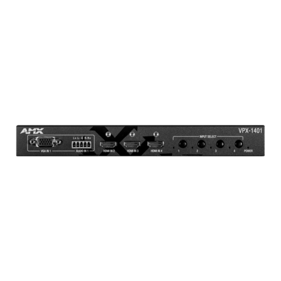
Page 9: Front Panel Description
LED: LED is located on the left of the selection button. When the button function is enabled, pressing an input selection buttonwill light the LED Green. POWER LED On: VPX-1401 is powered on. (Green) Off: VPX-1401 is powered off. User Manual - VPX-1401... -
Page 10: Rear Panel Description
: Connect to Ground. RESET When VPX-1401 is powered on, use a pointed stylus to hold down the RESET button for three or more seconds, and then release it. It will reboot and restore to its factory defaults. Connect to the power adapter provided. -
Page 11: Pinout Information
The following figures show the pinouts of the Phoenix Connectors. RS232&IR Connects to the RS232 and IR devices with the 6-pole, 3.5mm captive screw connectors. Audio IN/OUT Connect to an audio device with the 3-pole, 3.5mm captive screw connector. User Manual - VPX-1401... -
Page 12: Installation
Power on all attached devices. When all connections are made and power is ON, check if all LED indicators on the VPX-1401 are normal to ensure the installation is successful. For LED indication, please refer to the Panel Description section. - Page 13 User Manual - VPX-1401...
-
Page 14: Osd
Press and Hold the front panel buttons Input 1 and Input 2 for at least 3 seconds. The IP address of the VPX-1401 will display at the upper right of the connected display’s screen for about 15s and then disappear. -
Page 15: Input Source Switching
If you want to select a specific input port using input selection buttons: Disable Auto Switching through command setting or WEB UI on NetLinx. Press the appropriate Input Select Button to select a desired input port. When an inactive port is selected, the VPX-1401 will output no signal. -
Page 16: Ir Operation
Control the Source To control the source from the display location: Connect an IR emitter to IR port of the VPX-1401; Connect a broadband IR receiver to the IR IN port of an HDBT receiver. When the connections are complete, the source can be controlled at the display location through a source remote. -
Page 17: Rs232 Operation
The RS232 port of the VPX-1401 can be used for bi-directional RS232 signal pass-through between VPX-1401 and an HDBT receiver. To set up RS232 pass-through: Connect an RS232 Master (or Slave) Device to the RS232 port of the VPX-1401 with an RS232 cable (See Pinout Information Section for RS232 wiring);... -
Page 18: Netlinx Control
Device Number and Ports Each VPX-1401 has its own Device Number (which is assigned when the unit is bound to a Control System) and the following ports. Port 1: VGA IN 1 (AUDIO IN 1); HDMI OUT; HDBT OUT; AUDIO OUT... -
Page 19: Send Command To Control A Device
Click “Diagnostics” on the menu bar, select “Control a Device”. A window will display as follows, type the Device number, Port number, System and command respectively, and click “Send To Device”. (For API commands, see the Section API Command Set.) User Manual - VPX-1401... -
Page 20: Launch Telnet Window
* If you select “Launch TELENT Window via User Defined Program”, you may need to enable Telnet by completing the following: (1) go to Start/Control Panel/Programs and Features; (2) on the left, select “Turn Windows features on or off”; (3) select the check-boxes Telnet Client and Telnet Server, and click OK. User Manual - VPX-1401... -
Page 21: Web Ui Control Via Netlinx
Web UI Control via NetLinx To configure and control the device on the Web, right click the Device Number in the Online Tree Tab, choose “Web Control Page” – “Launch Web Control Page via NetLinx Studio”. User Manual - VPX-1401... -
Page 22: Web Ui Control
Web UI Control The Web UI designed for the VPX-1401 allows basic controls and advanced settings of the device. The Web UI page can be accessed through NetLinx Studio. To access the VPX-1401 Web UI: Connect your PC and the LAN port of the VPX-1401 to the same local area network. -
Page 23: Refresh
A successful reset will restore all the device settings to their factory defaults and the device will reboot automatically. Allow at least 2 minutes for the reboot to complete. Reboot The Reboot button is used to reboot the device. To reboot the device: Click “Reboot” button. Click “OK” to proceed. User Manual - VPX-1401... -
Page 24: Update Status
ON: Click to enable Auto Switch (default setting). • OFF: Click to disable Auto Switch. Key Lock Key Lock allows locking of the buttons on the VPX-1401 to prevent accidental or unwanted switching. • ON: Click to enable Key Lock. •... -
Page 25: Edid Support
Locate the target input port and select the settings from its drop-down menu, then click “Apply” to perform the setting. Display Control Auto Display Control Auto Display Control allows control of CEC-enabled displays connected to the VPX-1401 through HDMI. • ON: Click to enable the Auto Display Control. -
Page 26: Output Resolution Setting
DHCP: When enabled, the IP address of the VPX-1401 will be assigned automatically by the connected DHCP server. • Static: When the VPX-1401 fails to obtain or detect an IP address from the network to which it is connected, select “Static” to set up the IP address manually. -
Page 27: System
• SSH ACCOUNT The default user name is admin, the default password is password. Note: Reboot the device for the SSH ACCOUNT setting change to take effect. • APPLY: Click to choose each of the settings. User Manual - VPX-1401... -
Page 28: Firmware Upgrade
Verify the VPX-1401 unit is powered ON. Launch NetLinx Studio and open the Online Tree. Bind the device to the integrated Master: select and right-click the VPX-1401; from the context sensitive menu, select Network Bind/Unbind Device (be sure the check box is selected); click OK Transferring KIT Files In NetLinx Studio, choose Tools >... - Page 29 User Manual - VPX-1401...
-
Page 30: Troubleshooting
Troubleshooting Power: Ensure all devices are powered on. Indicator: Ensure all LED indicators of the VPX-1401 are normal according to the user manual. Devices: Ensure picture can be shown normally when directly connecting a source to a display device. Cable: Plug the HDMI/Cat X cable in and out or connect a different HDMI/Cat X cable. Ensure the specific cable length is within the available transmission range according to Specifications Section. -
Page 31: Api Command Set
Device Port Name and Port Number Model name Port name Port name VPX-1401 VGA IN 1 (Audio in 1) HDMI IN 2 HDMI IN 3 HDMI IN 4 RS-232 HDMI OUT HOST HDBT OUT Audio out Contact IN Tally Out User Manual - VPX-1401... - Page 32 To verify switch status SEND_COMMAND <DEV>, “’?INPUT’” SEND_COMMAND SWITCHER,”’?INPUT’” Return: Return: SWITCH-L<sl>I<input>O<output> SWITCH-ALL,I1,OALL. Description: Description: <sl> : {ALL}. HDMI IN1 routes to all outputs <input> 1: VGA IN; 2: HDMI IN1; 3: HDMI IN2; 4: HDMI IN3; <output> {ALL} User Manual - VPX-1401...
- Page 33 Define the display control automatically off. ?CEC_DISP_AUTO Command: Command: To verify the display SEND_COMMAND <DEV>, “’?CEC_DISP_ SEND_COMMAND SWITCHER,”’?CEC_DISP_ control Status AUTO’” AUTO’” Return: Return: CEC_DISP_AUTO-<ON|OFF> CEC_DISP_AUTO-ON Description: Get the display control Status. The display control Status is on. User Manual - VPX-1401...
- Page 34 HDMI IN1; HDMI IN2; HDMI IN3; <resolution> For VGA Input 1920x1200,60 1920x1080,60 1680x1050,60 1600x900,60 1440x900,60 1360x768,60 1280x768,60 1024x768,60 For HDMI Input 3840x2160,60 3840x2160,30 1920x1080,60 1280x720,60 1920x1200,60 1680x1050,60 1600x1200,60 1600x900,60 1440x900,60 1400x1050,60 1366x768,60 1280x1024,60 1280x960,60 1024x768,60 COPY User Manual - VPX-1401...
- Page 35 HDMI IN2; HDMI IN3; Command: Command: ?VIDIN_HDCP To Get Input HDCP SEND_COMMAND <DEV>,”’?VIDIN_HDCP’” SEND_COMMAND VIDEO_INPUT_3,”’?VIDIN_ Compliant Status HDCP’” Return: Return: VIDIN_HDCP-<ENABLE|DISABLE> VIDIN_HDCP-ENABLE Description: Input port: Description: HDMI IN2 is HDCP Compliant. HDMI IN1; HDMI IN2; HDMI IN3; User Manual - VPX-1401...
- Page 36 4096x2160,60 4096x2160,30 … … 1024x768,60 800x600,60 Command: Command: REBOOT To cause a warm reboot SEND_COMMAND <DEV>, “’REBOOT’” SEND_COMMAND 5002:1:0, “’REBOOT’” Return: Return: REBOOT SEND_COMMAND 5002:1:0, “’REBOOT’” Description: Description: Cause a warm reboot. Cause a warm reboot. User Manual - VPX-1401...
- Page 37 VIDOUT_SCALE-Auto Description: Scale mode as auto. Command: Command: VIDOUT_MUTE Set the video mute mode SEND_COMMAND <DEV>,”’VIDOUT_MUTE- SEND_COMMAND SWITCHER,”’VIDOUT_MUTE- for the video output port <ENABLE|DISABLE>’” ENABLE’” Return: Return: VIDOUT_MUTE<ENABLE|DISABLE> VIDOUT_MUTE-ENABLE Description: Set Video mute mode is enable. User Manual - VPX-1401...
- Page 38 Video on mode is disable. VIDOUT_RGB Command: Command: Set the video color SEND_COMMAND <DEV>,”’VIDOUT_RGB- SEND_COMMAND SWITCHER,”’VIDOUT_RGB- space for the video <ENABLE|DISABLE>’” ENABLE’” output port Return: Return: VIDOUT_RGB-<ENABLE|DISABLE> VIDOUT_RGB-ENABLE Description: Set Video out color space as RGB. User Manual - VPX-1401...
- Page 39 Audio max is 100. Command: Command: AUDOUT_MINVOL Set the audio min vol for SEND_COMMAND <DEV>, “’AUDOUT_ SEND_COMMAND AUDIO_OUTPUT_1, the audio output port MINVOL-<value>’” “’AUDOUT_MINVOL-5’” Return: Return: ‘AUDOUT_MINVOL-<value> AUDOUT_MINVOL-5 Description: Description: <value> = {0~100} Set Audio min as 5. User Manual - VPX-1401...
- Page 40 Set Audio vol as 50. Command: Command: ?AUDOUT_VOLUME Get the audio vol for the SEND_COMMAND <DEV>, “’?AUDOUT_ SEND_COMMAND AUDOUT_VOLUME_1, audio output port VOLUME’” “’?AUDOUT_VOLUME’” Return: Return: AUDOUT_VOLUME-<value> AUDOUT_VOLUME-50 Description: Description: <value> = {0~100} Audio volume is 50. User Manual - VPX-1401...
-
Page 41: Telnet/Ssh Commands
--- Enter New Values or just hit Enter to keep current settings Enter IP Address 192.168.2.201 192.168.2.202 Enter Netmask 255.255.240.0 255.255.255.0 --- New settings --- IP Address 192.168.2.202 Netmask 255.255.255.0 Would you like to save the new settings? Y/N -> y New settings were saved. User Manual - VPX-1401... - Page 42 Enable default [warning] system log level debug Enable all system debug messages info Enable info system log level warning Enable warning system log level error Enable error system log level Disable system log output to terminal session Example: msg on User Manual - VPX-1401...
- Page 43 Master Port 1319 Is this correct? Type Y or N and Enter -> Y Changed && Saved get connection Get the master >get connection connection settings. Connection Mode: Icsp_Auto System Number: Master Ip/URL Master Port: 1319 User Manual - VPX-1401...
- Page 44 Set ssh service login >set ssh password password Enter ssh new password password pass Would you like to set this password (y/n) Changed && Saved (you should reboot this device that make your setting active) User Manual - VPX-1401...
- Page 45 About AMX by HARMAN Founded in 1982 and acquired by HARMAN in 2014, AMX® is dedicated to providing AV solutions for an IT World. AMX solves the complexity of managing technology with reliable, consistent and scalable systems comprising control, video switching and distribution, digital signage and technology management. AMX systems are deployed worldwide in conference rooms, classrooms, network operation/command centers, homes, hotels, entertainment venues and broadcast facilities, among others.
Need help?
Do you have a question about the VPX-1401 and is the answer not in the manual?
Questions and answers