Table of Contents
Advertisement
Advertisement
Table of Contents

Subscribe to Our Youtube Channel
Related Manuals for ControlByWeb WebRelay X-WR-1R12-1I5-5


Summary of Contents for ControlByWeb WebRelay X-WR-1R12-1I5-5
- Page 2 WebRelay Users Manual WebRelay User Manual Revisions Revision Description Added changes for models X-WR-1R12-1I-I and X-WR-1R12-1I-E. Made minor changes to the digital input specification. Added documentation for new POE operation with external power applied. New document format, moved warranty and other information to the appendix. Moved XML and Modbus information to Section 5 Auxiliary Operations Added “Accessing the Internet”...
-
Page 3: Table Of Contents
WebRelay Users Manual Table of Contents Section 1: Introduction............................6 Remote Control and Monitoring......................6 Remote Reboot Controller ........................6 Applications............................6 1.1 Features..............................7 1.2 Applications............................. 8 1.3 Part Numbers and Accessories......................9 1.3.1 Optional Accessories.......................... 9 1.4 Security Notes............................9 1.5 Connectors &... - Page 4 WebRelay Users Manual 3.1.4.3Standard or Automatic Reboot Mode..................45 3.1.5 Control Page Setup (When Relay Mode is set to Standard).............49 3.1.6 Control Page Setup (When Relay Mode is set to Automatic Reboot)..........52 Section 4: Control Page............................. 55 4.1 Browser Operation (Standard Relay Mode)..................55 4.2 Browser Operation (Automatic Reboot Relay Mode).................57 Section 5: Auxiliary Operations.........................
- Page 5 WebRelay Users Manual Appendix H: Mechanical Dimensions....................... 81 Xytronix Research & Design, Inc. Page 5...
-
Page 6: Section 1: Introduction
Introduction WebRelay Users Manual Section 1: Introduction Remote Control and Monitoring WebRelay is an electromechanical relay with a built-in web server. It can be controlled and monitored over any IP network including private networks, IP- based industrial control networks, and the Internet. Stand-Alone Module Users can access and operate WebRelay using its built-in setup and control pages by using a standard web browser. -
Page 7: Features
WebRelay Users Manual 1.1 Features ➢ No Internet cloud services or fees required ➢ No programming required ➢ Built-in web server provides simple, web based configuration and control ➢ Control page can be customized with appropriate text and buttons. ➢ 10/100 Base-T Ethernet connectivity ➢... -
Page 8: Applications
Introduction WebRelay Users Manual 1.2 Applications The WebRelay was designed to meet a broad range of industrial applications. It works well as a stand- alone device that can be controlled using a web browser, or as a convenient way to add I/O to a computer or existing control system. -
Page 9: Part Numbers And Accessories
WebRelay Users Manual 1.3 Part Numbers and Accessories The WebRelay is currently available in two different models. Part Number Power Supply Requirements Digital Input X-WR-1R12-1I-I 9-28VDC 4-26 VDC X-WR-1R12-1I-E Power Over Ethernet and/or 9-28VDC 4-26 VDC X-WR-1R12-1I5-5 5VDC 4-12 VDC X-WR-1R12-1I5-I 9-28VDC 4-12 VDC... -
Page 10: Connectors & Indicators
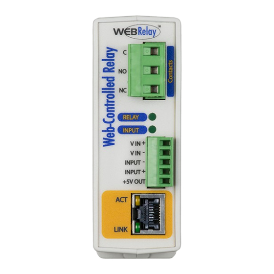
Introduction WebRelay Users Manual 1.5 Connectors & Indicators WebRelay has two removable terminal connectors and an Ethernet connector. The three-position terminal connector is used to connect the relay to the load. The five-position terminal connector provides power to the internal web server, and has connections for the optically-isolated input and +5VDC output. Relay The WebRelay has an internal high-current relay. - Page 11 WebRelay Users Manual The WebRelay has a five-position, removable screw terminal connector for power and input connections, the three-position connector provides connections to the internal relay. 5-Pin Connector Terminal Description Vin+ Power supply input + (not required for POE model) Do not exceed maximum power supply voltage (9-28VDC) Vin- Power input- (GND)
-
Page 12: Accessing The Webrelay Using A Web Browser
Introduction WebRelay Users Manual 1.6 Accessing the WebRelay using a Web Browser The WebRelay has a built-in web server that provides the user simple web pages that can be accessed directly using a standard web browser. This allows users to access the unit with NO SPECIAL SOFTWARE installed on their computer. -
Page 13: Section 2: Installation And Connections
WebRelay Users Manual Section 2: Installation and Connections Installation consists of mounting the WebRelay, connecting it to an Ethernet network, providing power, and connecting the relay contacts to the device that will be controlled. Optionally, a control signal may be connected to the optically-isolated input. The installation is completed by configuring the module using a web browser. -
Page 14: Din-Rail Mounting
Installation and Connections WebRelay Users Manual 2.1.2 DIN-Rail Mounting The WebRelay can be mounted to a standard (35mm by 7.55mm) DIN-Rail. Attach the WebRelay to the DIN-Rail by hooking the top hook on the back of the enclosure to the DIN-Rail and then snap the bottom hook into place. -
Page 15: Making Connections
WebRelay Users Manual 2.2 Making Connections CAUTION: Make sure the power is shut off before making connections CAUTION: This unit should be installed by a qualified technician. CAUTION: Miswiring or misconfiguration could cause permanent damage to the WebRelay, the equipment to which it is connected, or both. A removable terminal connector is provided for making the power connections. -
Page 16: Relay Connections (Control A Device Over An Ip Network)
Installation and Connections WebRelay Users Manual 2.3 Relay Connections (Control a device over an IP network) The Com, NC and NO relay contacts are internally connected directly to the terminal connector. No internal fuse is provided. If the power source connected to the relay contacts can deliver more than rated maximum contact current, an external fuse or circuit breaker must be used. -
Page 17: Digital Input Connections
WebRelay Users Manual 2.4 Digital Input Connections The digital input can be used to control the internal relay, control a remote relay (over the network), or simply to monitor the state of a discrete device. To use this input, connect a DC control voltage directly to the Input+ and Input- terminals, and set up the function of the input using the configuration pages. - Page 18 Installation and Connections WebRelay Users Manual Many of the illustrations in this manual show the WebRelay contacts wired in series with a power source, which allows the power for the device to be switched on and off remotely. In many cases, however, it is useful to control other functions and not just power.
-
Page 19: Dc Input Connections
WebRelay Users Manual 2.4.2 DC Input Connections The digital input is connected internally through a current-limiting resistor directly to a photo-coupler circuit. The photo coupler inputs isolated from the power supply circuits. No external resistor is necessary as long as the input signal is within the proper range (See Appendix D: Specifications). A DC voltage can be reduced with an external resistor of the appropriate value and power rating to reduce the input current. -
Page 20: Ac Input Connections
Installation and Connections WebRelay Users Manual 2.4.3 AC Input Connections If an AC signal voltage needs to be detected, use a signal conditioner to convert the AC signal to a DC voltage within the input range. An AC signal conditioner can be made using a diode (or bridge rectifier) and a capacitor. -
Page 21: Example Applications And Configurations
WebRelay Users Manual 2.5 Example Applications and Configurations Several basic installation schemes are illustrated in this section. 2.5.1 Single WebRelay Device (IP network control only) The example below shows the use of an interposer relay to control a load with larger current requirements than that provided by the 12-amp relay in the WebRelay. -
Page 22: Single Webrelay Device (Digital Input And/Or Ip Network Control)
Installation and Connections WebRelay Users Manual 2.5.2 Single WebRelay Device (digital input and/or IP network control) This configuration offers both network and local control. In the example, the light shown on the right can be controlled locally using a mechanical switch, or it can be controlled remotely over the IP network. The mechanical switch controls a 5 volt signal that is applied to the optically-isolated input. -
Page 23: Dual Webrelay Devices (No Computer Required)
WebRelay Users Manual 2.5.3 Dual WebRelay Devices (no computer required) This configuration is used to control devices remotely without a web browser, or to extend a digital signal to a remote location on the network. A control voltage applied to one WebRelay controls the relay contacts of another WebRelay at a remote location. -
Page 24: Multiple Webrelay Operation (No Computer Required)
Installation and Connections WebRelay Users Manual 2.5.4 Multiple WebRelay Operation (no computer required) For some applications, it is useful to for one WebRelay to control multiple WebRelays at remote locations. There is not a way to configure a single WebRelay to control multiple WebRelays directly, but it is possible to set up multiple WebRelays in a daisy-chain mode so that one WebRelay controls a second WebRelay which, in turn, controls a third WebRelay and so on. -
Page 25: Webrelay Used For Reboot (Wired In Series With Power)
WebRelay Users Manual 2.5.5 WebRelay Used for Reboot (wired in series with power) The illustration below shows an example of how WebRelay can be used to reboot a server. The WebRelay module is wired in series with the server's power source, which allows it to turn the server on and off. -
Page 26: Webrelay Used For Reboot (Wired To Reset)
Installation and Connections WebRelay Users Manual 2.5.6 WebRelay Used for Reboot (wired to reset) The illustration below shows how WebRelay can be wired to the reset circuit of a computer motherboard. In this scenario, the computer is never powered down, only reset when necessary by temporarily closing the relay contacts. -
Page 27: Network Connection
WebRelay Users Manual 2.5.8 Network Connection Connect the Ethernet port to a standard 10/100 Base-T Ethernet connection. The WebRelay typically connects to an Ethernet hub, switch, or router. The WebRelay does not support auto-negotiation on the Ethernet cable. For configuration, WebRelay may be connected directly to the Ethernet port on a computer using a “crossover”... -
Page 28: Establishing Communications For Setup
Method 2: Assign a temporary IP address to the WebRelay to work on an existing network. Note: If multiple ControlByWeb™ products are used on the same network, install one at a time and set the IP address of each unit before connecting the next unit to the network. This avoids having multiple devices being installed on the network with the same factory default IP address at the same time. - Page 29 WebRelay Users Manual 4. Select View network status and tasks. 5. Select Change adapter settings Xytronix Research & Design, Inc. Page 29...
- Page 30 Installation and Connections WebRelay Users Manual 6. Your machine may have more than one Internet connection shown. Right-click on the adapter for your connection to the internet. A drop-down box will appear, choose Properties to view/edit the settings for this internet connection. 7.
- Page 31 WebRelay Users Manual 8. If “Use the following IP address” is already selected, the computer has been setup with a static IP address. Record these values so that the current IP address of the computer can be restored once the IP address of the WebRelay has been successfully changed.
-
Page 32: Method 2: Assign A Temporary Ip Address To The Webrelay
Installation and Connections WebRelay Users Manual 2.6.2 Method 2: Assign a Temporary IP address to the WebRelay This option (arping) is used to TEMPORARILY assign an IP address to the WebRelay without the need to change the IP address of the configuration computer. The WebRelay will use this IP address as long as power is maintained. -
Page 33: Mac Os X Instructions
WebRelay Users Manual ping -s 102 10.10.10.40 4. Proceed with the WebRelay setup in Section 3. Once setup is complete, it may be necessary to clear the 'arp' cache to configure additional devices. This is necessary because each unit has the same default IP address, but a different unit serial number (MAC address). -
Page 34: Section 3: Web Server And Setup Pages
Web Server and Setup Pages WebRelay Users Manual Section 3: Web Server and Setup Pages WebRelay is fully configurable through HTML 4.0 compliant web browsers such as Chrome, Internet Explorer, and Mozilla Firefox. It has an easy-to-use, tab-based menu system. The internal web server presents two types of web pages;... -
Page 35: Main Setup Page
WebRelay Users Manual 3.1.1 Main Setup Page This is the initial page that appears when the following URL http://192.168.1.2/setup.html is entered into the web browser. It provides basic information about the WebRelay unit. Navigating between setup pages is done by clicking on the tabs at the top of the page. The setup pages require a password. -
Page 36: Network Setup Page
Web Server and Setup Pages WebRelay Users Manual 3.1.2 Network Setup Page The network parameters are changed on this page. Note that if multiple WebRelay units are used on the same network, install one unit at a time and set the IP address of each unit before connecting the next unit to the network. - Page 37 WebRelay Users Manual from LinkSys, Dlink, and Netgear perform proxy server functions. If a proxy server is used, WebRelay will not be accessible from the Internet until the proxy server is properly configured (forward proper port to WebRelay). This information is mentioned for convenience but details of setting up a configuration such as this is beyond the scope of this manual.
- Page 38 Web Server and Setup Pages WebRelay Users Manual SETTING BE LEFT AT 10MBPS UNLESS THE USER HAS A SPECIFIC REASON TO USE 100MBPS. Mode This option allows the Ethernet port to be set to Half Duplex or Full Duplex. Legacy Ethernet operates in Half Duplex mode which means that devices can either send data or receive data, but not both at the same time.
-
Page 39: Password Setup Page
WebRelay Users Manual 3.1.3 Password Setup Page The password setup page is used to change and enable passwords. A password is required for the setup pages but is optional for the control page. The password is enabled or disabled for the control page by using the Yes or No radio buttons. -
Page 40: Relay/Input Setup Page
Web Server and Setup Pages WebRelay Users Manual 3.1.4 Relay/Input Setup Page This page is used to set up the function of the relay and the control input. Note that in this manual, the relay is considered to be on when the relay coil is energized. When the relay coil is on, the normally open contacts are closed and the normally closed contacts are open. -
Page 41: 1Standard Relay Mode
WebRelay Users Manual device. The WebRelay expects a response after each ping. If a preset number of ping requests fail, it is assumed that the device is not functioning properly. The WebRelay will attempt to restore the device to normal operation by rebooting the device. In Automatic Reboot mode, users also have the ability to manually reboot the device from a remote location over the network. - Page 42 Web Server and Setup Pages WebRelay Users Manual latch relay when input on (reset via web) - When a voltage is applied to the input, the relay goes on. Once the relay is on it will stay on (unaffected by input changed) until it is turned off via the web by a user or the WebRelay is powered off.
-
Page 43: 2Automatic Reboot Mode
WebRelay Users Manual 3.1.4.2 Automatic Reboot Mode The following parameters are available only when the WebRelay is set to Automatic Reboot relay mode. Ping IP Address This is the IP address that WebRelay will ping. This is typically the IP address of the device that will be re-booted upon failure (such as a server, router, computer, etc.). - Page 44 Web Server and Setup Pages WebRelay Users Manual Unsuccessful Ping Period When ping requests fail (no response from device), it may be desirable to begin pinging at a shorter time interval. This allows the WebRelay to determine in less time that the device is not functioning. After each unsuccessful ping, the WebRelay will wait this time interval (in seconds) before the next ping attempt.
-
Page 45: 3Standard Or Automatic Reboot Mode
WebRelay Users Manual method #3 described above. In this case the power button is wired in parallel with the relay. Common and Normally Open contacts are used. When the device needs to be re-booted, the relay will be pulsed on for T1 (see above) seconds. After the first pulse, the relay will stay off for T2 seconds, and then pulse on for T3 seconds. - Page 46 Web Server and Setup Pages WebRelay Users Manual send on command when input off (no off command) - When a voltage is removed from the input, a command is sent to the remote WebRelay to set the relay state to on. When a voltage is applied to the input, no commands are sent to the remote WebRelay.
- Page 47 WebRelay Users Manual For a more technical description of this option, commands sent to remote WebRelay units look like this: http://192.168.1.2/state.xml?relayState=1 When a 0 is entered into this field, the above format is used which is required for standard WebRelay units.
- Page 48 Web Server and Setup Pages WebRelay Users Manual opposite of input, and remote command equals local relay. If any of the other ‘Remote Relay Options’ are selected, the state will not be transmitted. Note: When units are set up to require a control password, this password must be sent each time the state is updated.
-
Page 49: Control Page Setup (When Relay Mode Is Set To Standard)
WebRelay Users Manual 3.1.5 Control Page Setup (When Relay Mode is set to Standard) Once the WebRelay is set up, it can be controlled and monitored using a web browser by accessing its control page. Titles, colors, and basic contents of the control page can be customized by setting the appropriate options on the ‘Control Page Setup’... - Page 50 Web Server and Setup Pages WebRelay Users Manual Main Header Text This text will be displayed in the main header area of the control page. This field can be up to 25 characters in length. Relay Description This text is used to describe the function of the relay on the control page. This text will not appear if the ‘Display Relay Status’...
- Page 51 WebRelay Users Manual Input Description This is the text that will be displayed next to the input status when the ‘Display Input Status’ is enabled. It can be up to 20 characters in length. Input ON Color When ‘Display Input Status’ is set to Yes, this field specifies the color that will be displayed when the input is on (voltage applied to input).
-
Page 52: Control Page Setup (When Relay Mode Is Set To Automatic Reboot)
Web Server and Setup Pages WebRelay Users Manual 3.1.6 Control Page Setup (When Relay Mode is set to Automatic Reboot) Once the WebRelay is set up, it can be controlled and monitored using a web browser by accessing its control page. Titles, colors, and basic content of the control page can be customized by setting the appropriate options in the ‘Control Page Setup’... - Page 53 WebRelay Users Manual Relay Description This text is used to describe the function of the relay on the control page. This text will not appear if the ‘Display Relay Status’ is set to No, and ‘ON/OFF’ buttons are not displayed which allow relay control. This field can be up to 20 characters in length.
- Page 54 Web Server and Setup Pages WebRelay Users Manual When this option is set to Yes, the control page will display buttons to turn the device on and off. These buttons attempt to represent the state of the device and not the relay (the relay status however, represents the state of the relay).
-
Page 55: Section 4: Control Page
WebRelay Users Manual Section 4: Control Page The WebRelay can be operated using a web browser, by sending text commands to an XML status/control page, and/or by sending Modbus/TCP requests. The WebRelay can be controlled using inputs, or other relays. (Using an input to control the relay was described in the previous sections of the manual, and will not be described here.) 4.1 Browser Operation (Standard Relay Mode) Once the WebRelay is set up, users can access the Control Page using a web browser. - Page 56 Control Page WebRelay Users Manual Description field in the Control Page Setup tab. The state of the relay is shown to the right of the relay description text. By default, the status text will read Relay ON or Relay OFF; however, the status text can be changed in the Control Page Setup tab.
-
Page 57: Browser Operation (Automatic Reboot Relay Mode)
WebRelay Users Manual 4.2 Browser Operation (Automatic Reboot Relay Mode) The control page for automatic reboot mode is accessed the same as it is in standard mode. See Section 4.1 for information on accessing the control page. Using the Automatic Reboot control page is simple and straightforward. Control pages will vary based upon options selected in setup. - Page 58 Control Page WebRelay Users Manual Reboot State Description After power-up, the WebRelay will wait for the device to boot before sending any ping requests. The “Waiting for boot” message is displayed during this wait time. The wait time is specified in the ‘Delay Before First Ping After Reboot’ parameter under the ‘Relay/Input’...
-
Page 59: Section 5: Auxiliary Operations
WebRelay Users Manual Section 5: Auxiliary Operations 5.1 XML Custom computer applications may be created to monitor and control WebRelay without using a web browser. Monitoring the state of the input and the relay is done by sending a request to port 80 (or port specified in setup) for the XML page. -
Page 60: Xml Control
Auxiliary Operations WebRelay Users Manual XML Tags* Monitor Values <totalreboots> This field indicates the number of times WebRelay has automatically rebooted the device that it is controlling. Note: This counter only increments when reboots are initiated by the automatic reboot controller. This value can be cleared by sending a clear command or is automatically cleared whenever WebRelay loses power. -
Page 61: Message Acknowledgment
WebRelay Users Manual The pulseTime variable does not change the pulse time specified in the setup page and it is not stored or recorded. The pulseTime variable only changes the pulse duration for the single pulse initiated by that command. In other words, you must issue the pulseTime for each pulse command that differs from the preset pulse time. -
Page 62: Http Get Requests (For Custom Applications)
Where bm9uZTp3ZWJyZWxheQ== is the base 64 encoded version of the username and password none:webrelay A utility is provided at http://www.ControlByWeb.com/encoder that can be used to encode the password. The utility is used by simply typing the string username:password into the website and pressing encode. -
Page 63: Modbus/Tcp
WebRelay Users Manual 5.3 Modbus/TCP The WebRelay can be controlled and monitored using Modbus/TCP protocol. This provides a standard means of using the WebRelay with devices and software from other manufacturers. This section is not a tutorial on Modbus and it is assumed that the reader is already familiar with Modbus. Detailed Modbus information can be found at http://www.modbus.org. -
Page 64: Webrelay Full Address Table
Auxiliary Operations WebRelay Users Manual Code Name Modbus Data Type* PLC Address PLC Address Function Mode 485 Mode 584/984 Coils (Read/Write) 01, 05 Discrete 1-1000 1-10000 Discrete Inputs (Read only) Discrete 1001-2000 10001-20000 Registers (Read only) 8-64 bits 3001-4000 30001-40000 Holding Registers 8-64 bits 4001-5000... -
Page 65: Read Coils - Modbus Function Code 01 (0X01)
WebRelay Users Manual 5.3.4 Read Coils - Modbus Function Code 01 (0x01) Read the state of the relay coil. In addition, the optically-isolated digital input can be read using this function which allows the full state of the WebRelay to be read in a single transaction. Request Start Address: 0x0000 or 0x0001 Coil Quantity: 0x0001 or 0x0002... -
Page 66: Read Discrete Inputs - Modbus Function Code 02 (0X02)
Auxiliary Operations WebRelay Users Manual 5.3.5 Read Discrete Inputs – Modbus Function Code 02 (0x02) This function returns the state of the digital input. Request Start Address: 0x0000 (always 0x0000) Input Quantity: 0x0001 (always 0x0001) Response The input state is indicated by bit one of the status byte. A “1” indicates that the input is ON. A “0”... -
Page 67: Write Single Coil - Modbus Function Code 05 (0X05)
WebRelay Users Manual 5.3.6 Write Single Coil Modbus Function Code 05 (0x05) – Control the relay Request Start Address (2 bytes): 0x0000 (Relay) Output Value (1 byte): 0x00 (OFF), 0xFF(ON) Padding (1 byte): 0x00 Response The response mirrors the requested state, 0x00 or 0xFF. Errors Single Coil Write Error Function Code (1 Byte): 0x85 Exception codes (1 Byte):... -
Page 68: Write Multiple Registers - Modbus Function Code 16 (0X10)
Auxiliary Operations WebRelay Users Manual 5.3.7 Write Multiple Registers – Modbus Function Code 16 (0x10) The Modbus Write Multiple Registers function is used to pulse the relay for a specified time. When the WebRelay receives this command, it immediately turns the relay coil on (if it is not on already on) and starts the pulse timer. -
Page 69: Appendix A: Restoring Factory Default Settings
WebRelay Users Manual Appendix A: Restoring Factory Default Settings In the event that the IP address or passwords are forgotten, the WebRelay may be restored to its original factory default settings. 1. Remove the DC power from the unit. 2. Use a thin, non-conductive object (such as a toothpick) to press and hold the small button located on the bottom of the unit. -
Page 70: Appendix B: Installing New Firmware
Setup 1. Download the firmware zip file from the ControlByWeb website. Only a WebRelay image can be installed on the WebRelay so make sure the correct image is being downloaded. 2. bootloader.exe will connect to the WebRelay using default IP address 192.168.1.2, not the address currently assigned to the WebRelay. - Page 71 3. While holding the reset button, apply power to WebRelay. The LINK and ACT lights will flash. Continue to hold the reset button for the next step. 4. While holding the reset button, press the Upload Firmware button at the bottom of the ControlByWeb™ Programmer window. After the programming process begins, the reset button can be released.
-
Page 72: Appendix C: Accessing The Webrelay Over The Internet
Appendix C: Accessing the WebRelay Over the Internet WebRelay Users Manual Appendix C: Accessing the WebRelay Over the Internet The WebRelay can be monitored and/or controlled from a remote location over the Internet. Once the WebRelay can be accessed on the local network, almost all of the settings required to provide remote access are in the router and not in the WebRelay. -
Page 73: A Simple Lan Connected To The Internet
65235. However, many port numbers are reserved for specific applications and should be avoided. As a general rule, numbers above 8000 are safe to use. All of the ControlByWeb products come from the factory with the HTTP port set to 80, which is the standard port for HTTP. In this example, the X- 310S HTTP port will be changed to port 8000 and WebRelay port will be changed to 8001. -
Page 74: Accessing Setup Pages
To access the ControlByWeb units from the Internet, enter the public IP address of the router plus the port number of the desired device in the following format: http://(Public IP Address of Router):(Port Number of Device)/setup.html Using the example above, the following line would be used to access the setup page of the WebRelay: http://266.70.164.97:8001/setup.html... -
Page 75: Appendix D: Specifications
WebRelay Users Manual Appendix D: Specifications Power Requirements Input Voltage: X-WR-1R12-1I-I: 9-28 VDC X-WR-1R12-1I5-I: 9-28 VDC X-WR-1R12-1I24-I: 9-28 VDC X-WR-1R12-1I-E: Power Over Ethernet and/or 9-28VDC 48V injected into Ethernet Line as per 802.3af specification POE Class 1 (0.44Watt to 3.84Watt range) X-WR-1R12-1I5-E: Power Over Ethernet or 5VDC 48V injected into Ethernet Line as per 802.3af specification POE Class 1 (0.44Watt to 3.84Watt range) - Page 76 Appendix D: Specifications WebRelay Users Manual X-WR-1R12-1I5-I and and X-WR-1R12-1I5-5 and X-WR-1R12-1I5-E Input Current (Iin): 4mA @ 4V, 16mA @ 12V Vin: 4-12 VDC X-WR-1R12-1I24-I Input Current (Iin): 3.2mA @ 11V, 8.2mA @ 26V Vin: 11-26 VDC Input Functions: Monitor, local relay control, remote relay control Input to Local Relay Settings: Equal, invert, toggle, latch, pulse, none Input to Remote Relay Settings:...
- Page 77 WebRelay Users Manual Nonvolatile Memory All user settings are stored in nonvolatile Flash memory. Settings will not be lost when power is disconnected. Password Settings Password protection on setup page: Yes Password protection on control page: Optional Password Encoding: Base 64 Max password length: 10 characters Environmental Operating Temperature:...
-
Page 78: Appendix E: Trademark And Copyright Information
Appendix E: Trademark and Copyright Information This document is Copyright ©2005-2018 by Xytronix Research & Design, Inc. All rights reserved. WebRelay™, ControlByWeb™, and Xytronix Research & Design™ are trademarks of Xytronix Research & Design™, Inc. 2005-2018. All other trademarks are the property of their respective owners. -
Page 79: Appendix F: Warranty
For warranty service or repair, customer must contact Xytronix Research & Design, Inc. technical support (support@ControlByWeb.com) and obtain a Return Authorization number (RA#). Before issuing an RA#, a support technician will work with customer to try to resolve the issue without returning the product. -
Page 80: Appendix G: Fcc Statement
Appendix G: FCC Statement WebRelay Users Manual Appendix G: FCC Statement This device complies with Part 15 of the FCC Rules. Operation is subject to the following two conditions: 1. This device may not cause harmful interference. 2. This device must accept any interference received, including interference that may cause undesired operation. - Page 81 WebRelay Users Manual Appendix H: Mechanical Dimensions Note: A 3D-CAD model is available at www.ControlByWeb.com Xytronix Research & Design, Inc. Page 81...
Need help?
Do you have a question about the WebRelay X-WR-1R12-1I5-5 and is the answer not in the manual?
Questions and answers