GORMAN-RUPP 0 SERIES Installation, Operation And Maintenance Manual
Hide thumbs
Also See for 0 SERIES:
Table of Contents
Advertisement
Quick Links
BC
OM‐01087‐02
April 8, 1981
Rev. B 05‐30‐13
INSTALLATION, OPERATION,
AND MAINTENANCE MANUAL
WITH PARTS LIST
0 SERIES PUMP
MODEL
02C3-B
THE GORMAN‐RUPP COMPANY D MANSFIELD, OHIO
www.grpumps.com
D
GORMAN‐RUPP OF CANADA LIMITED
ST. THOMAS, ONTARIO, CANADA
Printed in U.S.A.
e
2009 The Gorman‐Rupp Company
Advertisement
Table of Contents

Related Manuals for GORMAN-RUPP 0 SERIES


Summary of Contents for GORMAN-RUPP 0 SERIES
- Page 1 OM‐01087‐02 April 8, 1981 Rev. B 05‐30‐13 INSTALLATION, OPERATION, AND MAINTENANCE MANUAL WITH PARTS LIST 0 SERIES PUMP MODEL 02C3-B THE GORMAN‐RUPP COMPANY D MANSFIELD, OHIO www.grpumps.com GORMAN‐RUPP OF CANADA LIMITED ST. THOMAS, ONTARIO, CANADA Printed in U.S.A. 2009 The Gorman‐Rupp Company...
- Page 2 Register your new Gorman‐Rupp pump online at www.grpumps.com Valid serial number and e‐mail address required. RECORD YOUR PUMP MODEL AND SERIAL NUMBER Please record your pump model and serial number in the spaces provided below. Your Gorman‐Rupp distributor needs this information when you require parts or service. Pump Model: Serial Number:...
-
Page 3: Table Of Contents
TABLE OF CONTENTS INTRODUCTION ..........PAGE I - 1 SAFETY ‐... - Page 4 TABLE OF CONTENTS (continued) PUMP MAINTENANCE AND REPAIR ‐ SECTION E ....PAGE E - 1 STANDARD PERFORMANCE CURVE ........PAGE E - 1 PARTS LIST: Pump Model...
-
Page 5: Introduction
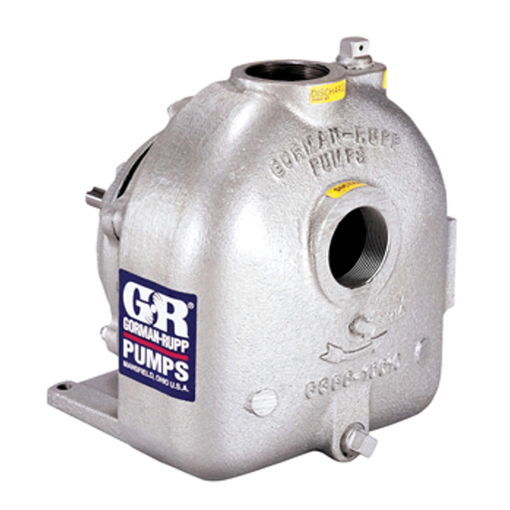
This pump is an 0 Series, closed impeller, self‐prim ing centrifugal model, with straight‐in suction, with out a suction check valve. It is designed to handle petroleum products or other clean liquids that do not contain large entrained solids. -
Page 6: Safety - Section A
0 SERIES OM-01087 SAFETY ‐ SECTION A This information applies to 0 Series ba sic pumps. Gorman‐Rupp has no con trol over or particular knowledge of the power source which will be used. Refer This pump is designed to handle petro... - Page 7 OM-01087 0 SERIES tional Electric Code and all local codes. If there is a conflict between the instruc tions in the manual accompanying the unit and the National Electric Code or Do not operate the pump against a the applicable local code, the National closed discharge valve for long periods or local code shall take precedence.
-
Page 8: Installation - Section B
0 SERIES OM-01087 INSTALLATION - SECTION B Review all SAFETY information in Section A. configuration, and priming must be tailored to the specific application. Since the pressure supplied Since pump installations are seldom identical, this to the pump is critical to performance and safety,... -
Page 9: Positioning Pump
OM-01087 0 SERIES AND REPAIR section of this manual and per The pump may have to be supported or shimmed form duties as instructed. to provide for level operation or to eliminate vibra tion. e. If the pump and engine have been stored for SUCTION AND DISCHARGE PIPING more than 12 months, some of the compo... -
Page 10: Suction Lines
0 SERIES OM-01087 ommendations when selecting and applying the SUCTION LINES pipe dope. The pipe dope should be compatible with the liquid being pumped. To avoid air pockets which could affect pump prim ing, the suction line must be as short and direct as Suction Lines In Sumps possible. -
Page 11: Discharge Lines
OM-01087 0 SERIES Figure 2. Recommended Minimum Suction Line Submergence vs. Velocity DISCHARGE LINES head, gradually close the discharge throttling valve before stopping the pump. Siphoning ALIGNMENT Do not terminate the discharge line at a level lower than that of the liquid being pumped unless a si... -
Page 12: Coupled Drives
0 SERIES OM-01087 When checking alignment, disconnect the power source to ensure that the pump will remain inoperative. Figure 3B. Aligning Non‐Spider Type Couplings Adjusting the alignment in one direction Align non‐spider type couplings by using a feeler may alter the alignment in another direc... -
Page 13: Drive Belt Tensioning
OM-01087 0 SERIES Tighten the belts in accordance with the belt manu Ideal drive belt tension is the lowest tension at facturer's instructions. If the belts are too loose, which the belt will not slip under peak load condi they will slip; if the belts are too tight, there will be tions. -
Page 14: Operation - Section C
OM-01087 0 SERIES OPERATION - SECTION C Review all SAFETY information in Section A. coming liquid to evacuate the air. After the pump and piping system have completely filled, evacu Follow the instructions on all tags, labels and ate any remaining air pockets in the pump or suc... -
Page 15: Operation
OM-01087 0 SERIES ature supplied with the motor for specific instruc Overheating can occur if operated with the valves tions. in the suction or discharge lines closed. Operating against closed valves could bring the liquid to a boil, build pressure, and cause the pump to rup... -
Page 16: Stopping
OM-01087 0 SERIES Before checking for the source of the leak, check Checking bearing temperatures by hand is inaccu the point of installation of the vacuum gauge. rate. Bearing temperatures can be measured ac curately by placing a contact‐type thermometer against the housing. -
Page 17: Troubleshooting - Section D
OM-01087 0 SERIES TROUBLESHOOTING - SECTION D Review all SAFETY information in Section A. Before attempting to open or service the pump: 1. Familiarize yourself with this manual. 2. Disconnect or lock out the power source to ensure that the pump will remain inoperative. - Page 18 OM-01087 0 SERIES TROUBLE POSSIBLE CAUSE PROBABLE REMEDY PUMP STOPS OR Suction intake not submerged at Check installation and correct FAILS TO DELIVER proper level or sump too small. submergence as needed. RATED FLOW OR Impeller or other wearing parts worn Replace worn or damaged parts.
-
Page 19: Preventive Maintenance
OM-01087 0 SERIES PREVENTIVE MAINTENANCE equipped) between regularly scheduled inspec tions can indicate problems that can be corrected Since pump applications are seldom identical, and before system damage or catastrophic failure oc pump wear is directly affected by such things as curs. - Page 20 0 SERIES OM-01087 PUMP MAINTENANCE AND REPAIR ‐ SECTION E MAINTENANCE AND REPAIR OF THE WEARING PARTS OF THE PUMP WILL MAINTAIN PEAK OPERATING PERFORMANCE. STANDARD PERFORMANCE FOR PUMP MODEL 02C3-B Based on 70_ F (21_ C) clear water at sea level Contact the Gorman‐Rupp Company to verify per...
- Page 21 OM-01087 0 SERIES SECTION DRAWING PARTS PAGE Figure 1. 02C3-B Pump Model Assembly PAGE E - 2 MAINTENANCE & REPAIR...
- Page 22 0 SERIES OM-01087 PARTS LIST Pump Model 02C3-B (From S/N 259749 Up) If your pump serial number is followed by an “N”, your pump is NOT a standard production model. Contact the Gorman‐Rupp Company to verify part numbers. ITEM PART...
- Page 23 OM-01087 0 SERIES PUMP AND SEAL DISASSEMBLY 4. Check the temperature before opening any covers, plates, or AND REASSEMBLY plugs. Review all SAFETY information in Section A. 5. Close the suction and discharge valves. Follow the instructions on all tags, label and de...
- Page 24 0 SERIES OM-01087 impeller vanes, being careful not to damage the stationary element and seat out of the intermediate vanes. Disengage the impeller nut (27). from the back side. Remove the slinger ring (20). Install the shaft key (15). Install a lathe dog on the drive end of the shaft (16) with the “V”...
- Page 25 OM-01087 0 SERIES The bearings may be heated to ease installation. flammable. Use them only in a well ven An induction heater, hot oil bath, electric oven, or tilated area free from excessive heat, hot plate may be used to heat the bearings. Bear...
- Page 26 0 SERIES OM-01087 Install the same thickness of bearing adjusting during reassembly. This could result in premature shims (18) as previously removed. Reinstall the re failure. If necessary to reuse an old seal in an emer taining ring (17) and check the shaft endplay.
- Page 27 OM-01087 0 SERIES RETAINER BEARING SPRING HOUSING SPRING RETAINER IMPELLER IMPELLER ROTATING SHAFT ELEMENT IMPELLER STATIONARY SHIMS ELEMENT BELLOWS STATIONARY SEAT DRIVE BAND Figure 3. Seal Assembly Subassemble the rotating element into the retainer and bellows. Lubricate the I.D. of the bellows with water and slide this subassembly onto the shaft until the polished faces contact.
- Page 28 0 SERIES OM-01087 Step 1 Step 2 Step 3 Figure 4. Centering Impeller Within Vane Plate Scroll Install the correct thickness of impeller shims (14) Final Pump Assembly and screw the impeller onto the shaft until fully Install the suction and discharge lines and open all seated.
- Page 29 For U.S. and International Warranty Information, Please Visit www.grpumps.com/warranty or call: U.S.: 419-755-1280 International: +1-419-755-1352 For Canadian Warranty Information, Please Visit www.grcanada.com/warranty or call: 519-631-2870 THE GORMAN‐RUPP COMPANY D MANSFIELD, OHIO GORMAN‐RUPP OF CANADA LIMITED ST. THOMAS, ONTARIO, CANADA...
Need help?
Do you have a question about the 0 SERIES and is the answer not in the manual?
Questions and answers