Table of Contents
Advertisement
Quick Links
Advertisement
Table of Contents

Related Manuals for GORMAN-RUPP T6A60S-4045T-ESP


Summary of Contents for GORMAN-RUPP T6A60S-4045T-ESP
- Page 1 OM-06331-01 January 18, 2010 Rev. B 03‐18‐15 INSTALLATION, OPERATION, AND MAINTENANCE MANUAL WITH PARTS LIST SUPER T SERIESr ENVIRONMENTAL SILENT PUMP MODEL T6A60S-4045T-ESP GORMAN‐RUPP PUMPS www.grpumps.com 2010 Gorman‐Rupp Pumps Printed in U.S.A.
- Page 2 Register your new Gorman‐Rupp pump online at www.grpumps.com Valid serial number and e‐mail address required. The engine exhaust from this product contains chemicals known to the State of California to cause cancer, birth defects or other reproductive harm. RECORD YOUR PUMP MODEL AND SERIAL NUMBER Please record your pump model and serial number in the spaces provided below.
-
Page 3: Table Of Contents
TABLE OF CONTENTS INTRODUCTION ..........PAGE I - 1 SAFETY ‐... - Page 4 TABLE OF CONTENTS (continued) Lines With a Bypass ........... . PAGE C - 5 Lines Without a Bypass .
-
Page 5: Introduction
SUPER T SERIES OM-06331 INTRODUCTION Thank You for purchasing a Gorman‐Rupp pump. HAZARD AND INSTRUCTION Read this manual carefully to learn how to safely DEFINITIONS install and operate your pump. Failure to do so could result in personal injury or damage to the The following are used to alert maintenance per... -
Page 6: Safety - Section A
SUPER T SERIES OM-06331 SAFETY ‐ SECTION A This information applies to Super T Se forming any maintenance. Failure to do riesr engine driven pumps. Refer to the so may result in serious personal injury. manual accompanying the engine be fore attempting to begin operation. - Page 7 OM-06331 SUPER T SERIES deteriorate, and the liquid could come to a boil, build pressure, and cause the pump casing to rupture or explode. Fuel used by internal combustion en gines presents an extreme explosion and fire hazard. Make certain that all Do not remove plates, covers, gauges, fuel lines are securely connected and pipe plugs, or fittings from an over...
-
Page 8: Installation - Section B
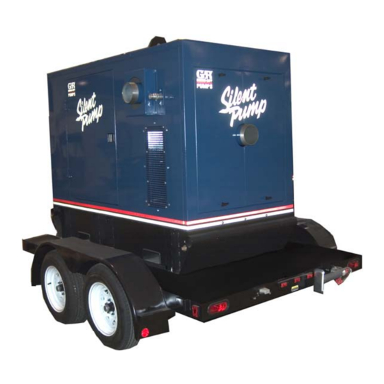
See Figure 1 for the approximate physical dimen configuration, and priming must be tailored to the sions of this pump. OUTLINE DRAWING Figure 1. Pump Model T6A60S-4045T-ESP PREINSTALLATION INSPECTION a. Inspect the pump assembly for cracks, dents, damaged threads, and other obvious dam... -
Page 9: Battery Specifications And Installation
OM-06331 SUPER T SERIES ing, check for loose hardware at mating sur sion. Connect and tighten the positive cable first, faces. then the negative cable. c. Carefully read all tags, decals, and markings POSITIONING PUMP on the pump assembly, and perform all duties indicated. -
Page 10: Clearance
SUPER T SERIES OM-06331 tion. The pump and engine may be positioned up and increased shaft and seal wear. If hose‐type to 30 off horizontal for intermittent operation lines are used, they should have adequate support only; however, the engine manufacturer should be to secure them when filled with liquid and under consulted for continuous operation at angles pressure. -
Page 11: Sealing
OM-06331 SUPER T SERIES This pump is designed to handle up to 3‐inch (76,2 suction inlet at a distance 1‐1/2 times the diameter mm) diameter spherical solids. of the suction pipe. The baffle will allow entrained air to escape from the liquid before it is drawn into the suction inlet. -
Page 12: Float Switches
SUPER T SERIES OM-06331 Figure 2. Recommended Minimum Suction Line Submergence vs. Velocity FLOAT SWITCHES above the point where it bends along the bot tom. Direct the suction line toward the flow, and the float(s) away from the flow. If a stand Installation pipe is available, attach the float switch cable to the standpipe in the sump at the approxi... -
Page 13: Optional Submersible Transducer
OM-06331 SUPER T SERIES ENGINE (0.9) CONTROL (.76) (Emptying) (0.6) (Filling) (.46) OPERATING (0.3) RANGE CABLE (See Table Below) TETHER (.15) POINT (Emptying) (0.3) (0.6) (0.9) (1.2) APPROXIMATE FREE CORD LENGTH IN FT. (M) 1.25” Pipe (Filling) (Not Furnished) Figure 3. Float Switch Data OPTIONAL SUBMERSIBLE above the point where it bends along the bot... -
Page 14: Discharge Lines
SUPER T SERIES OM-06331 SUCTION LINE DISCHARGE LINE SIGNAL CABLE (ATTACH TO SUCTION LINE) SUCTION SUBMERSIBLE STRAINER TRANSDUCER (DOWNSTREAM FROM SUCTION) FLOW Figure 4. Typical Submersible Transducer Installation DISCHARGE LINES Siphoning If the application involves a high discharge head, gradually close the discharge Do not terminate the discharge line at a level lower throttling valve before stopping the pump. -
Page 15: Automatic Air Release Valve
OM-06331 SUPER T SERIES affect pump discharge capacity; however, the by stalled anywhere in a bypass line, it must pass line should be at least 1 inch (25,4 mm) in di be a full‐opening, ball‐type valve to pre ameter to minimize the chance of plugging. vent plugging by solids. -
Page 16: Alignment
SUPER T SERIES OM-06331 Air Release Valve Installation tween the pump discharge port and the inlet side of the discharge check valve (see Figure 5). The inlet The Automatic Air Release Valve must be inde opening in the Air Release Valve is equipped with pendently mounted in a horizontal position be... -
Page 17: Operation - Section C
OM-06331 SUPER T SERIES OPERATION - SECTION C OPERATION Review all SAFETY information in Section A. Make sure the pump is level. Lower jack Follow the instructions on all tags, labels and stands and chock the wheels, if so decals attached to the pump. equipped. - Page 18 OM-06331 SUPER T SERIES Add liquid to the pump casing when: continuous operating speed for this pump. 1. The pump is being put into service for the first time. A Gorman‐Rupp automatic air release valve may 2. The pump has not been used for a consider be installed in a bypass line, or the bypass line may able length of time.
- Page 19 OM-06331 SUPER T SERIES before servicing it. Approach any over‐heated OPERATION IN EXTREME HEAT pump cautiously. The safety shutdown system will automatically stop the unit if engine operating temperature ex ceeds design limits. If engine over‐temperature shutdown occurs, allow the unit to cool before re Allow an over‐heated pump to com...
- Page 20 OM-06331 SUPER T SERIES Automatic Stopping Bearing Temperature Check Bearings normally run at higher than ambient tem In the automatic mode, the pump will stop when peratures because of heat generated by friction. the liquid in the wet well or sump lowers and acti Temperatures up to 160 F (71 C) are considered...
-
Page 21: Operation
OM-06331 SUPER T SERIES for approximately one minute; this will remove any large solids from clogging the drain port and pre remaining liquid that could freeze the pump rotat venting the pump from completely draining, insert ing parts. If the pump will be idle for more than a a rod or stiff wire in the drain port, and agitate the few hours, or if it has been pumping liquids con... - Page 22 SUPER T SERIES OM-06331 TROUBLESHOOTING - SECTION D Review all SAFETY information in Section A. 5. Close the suction and discharge valves. 6. Vent the pump slowly and cau tiously. 7. Drain the pump. Before attempting to open or service the pump: 1.
- Page 23 OM-06331 SUPER T SERIES TROUBLE POSSIBLE CAUSE PROBABLE REMEDY PUMP STOPS OR FAILS Impeller or other wearing parts Replace worn or damaged parts. TO DELIVER RATED worn or damaged. Check that impeller is properly cen tered and rotates freely. FLOW OR PRESSURE (cont.) Impeller clogged.
- Page 24 SUPER T SERIES OM-06331 equipped) between regularly scheduled inspec PREVENTIVE MAINTENANCE tions can indicate problems that can be corrected Since pump applications are seldom identical, and before system damage or catastrophic failure oc pump wear is directly affected by such things as curs.
- Page 25 OM-06331 PUMP MAINTENANCE AND REPAIR ‐ SECTION E MAINTENANCE AND REPAIR OF THE WEARING PARTS OF THE PUMP WILL MAINTAIN PEAK OPERATING PERFORMANCE. STANDARD PERFORMANCE FOR PUMP MODEL T6A60S-4045T-ESP Based on 70 F (21 C) clear water at sea level Contact the Gorman‐Rupp Company to verify per...
- Page 26 OM-06331 SUPER T SERIES ILLUSTRATION PARTS PAGE Figure 1. Pump Model T6A60S-4045T-ESP PAGE E - 2 MAINTENANCE & REPAIR...
- Page 27 SUPER T SERIES OM-06331 PARTS LIST Pump Model T6A60S-4045T-ESP (From S/N 1473164 Up) If your pump serial number is followed by an “N”, your pump is NOT a standard production model. Contact the Gorman‐Rupp Company to verify part numbers. ITEM...
- Page 28 OM-06331 SUPER T SERIES ILLUSTRATION Figure 2. Pump Model T6A60S-4045T-ESP (Cont'd) PAGE E - 4 MAINTENANCE & REPAIR...
- Page 29 SUPER T SERIES OM-06331 PARTS LIST Pump Model T6A60S-4045T-ESP (From S/N 1473164 Up) If your pump serial number is followed by an “N”, your pump is NOT a standard production model. Contact the Gorman‐Rupp Company to verify part numbers. ITEM...
- Page 30 OM-06331 SUPER T SERIES ILLUSTRATION Figure 3. Pump Model T6A60S-4045T-ESP (Cont'd) PAGE E - 6 MAINTENANCE & REPAIR...
- Page 31 SUPER T SERIES OM-06331 PARTS LIST Pump Model T6A60S-4045T-ESP (From S/N 1473164 Up) If your pump serial number is followed by an “N”, your pump is NOT a standard production model. Contact the Gorman‐Rupp Company to verify part numbers. ITEM...
- Page 32 OM-06331 SUPER T SERIES ILLUSTRATION Figure 4. T6A60S-(4045T-ESP) Pump End Assembly PAGE E - 8 MAINTENANCE & REPAIR...
- Page 33 SUPER T SERIES OM-06331 PARTS LIST T6A60S-(4045T-ESP) Pump End Assembly ITEM PART NAME PART ITEM PART NAME PART NUMBER NUMBER PUMP CASING SEE NOTE BELOW HEX HD CAPSCREW B0604 15991 REPAIR ROTATING ASSY 44163-349 LOCKWASHER J06 15991 CLAMP BAR SCREW 31912-009 15000 HEX NUT D06 15991...
- Page 34 OM-06331 SUPER T SERIES ILLUSTRATION Figure 5. Repair Rotating Assembly PAGE E - 10 MAINTENANCE & REPAIR...
- Page 35 SUPER T SERIES OM-06331 PARTS LIST Repair Rotating Assembly ITEM PART PART NAME NUMBER IMPELLER 38615-087 11010 SEAL ASSEMBLY 46513-154 SEAL PLATE 38272-254 10010 OIL SEAL S1917 OIL SEAL S1917 OIL SEAL S1917 SEAL PLATE GSKT 10959G 20000 HEX HD CAPSCREW B0805 ½...
- Page 36 OM-06331 SUPER T SERIES ILLUSTRATION Figure 6. Check Valve/Air Release Assembly PAGE E - 12 MAINTENANCE & REPAIR...
- Page 37 SUPER T SERIES OM-06331 PARTS LIST Check Valve/Air Release Assembly ITEM PART PART NAME NUMBER 6'' ELBOW 38647-905 10010 PIPE NIPPLE T1616 15079 PIPE ELBOW R16 11999 CLOSE PIPE NIPPLE T16 15079 1.00 BALL VALVE 26631-024 HEX HEAD CAP SCREW B0503 15991 FLAT WASHER K05 15991...
- Page 38 OM-06331 SUPER T SERIES ILLUSTRATION MODEL T6A60S LOCATE COUPLING AS DIMENSIONED Figure 7. Drive Assembly PARTS LIST ITEM PART PART NAME NUMBER COUPLING KIT 48112-001 -BUSHING 24131-345 -COUPLING ASSEMBLY 44165-011 -LOCKWASHER J06 15991 -LOCKWASHER 21171-536 -SOCKET HD CAPSCREW BD0606-1/2 15991 -SOCKET HD CAPSCREW 22644-220 HEX HD CAPSCREW...
- Page 39 SUPER T SERIES OM-06331 PUMP AND SEAL DISASSEMBLY AND REASSEMBLY Review all SAFETY information in Section A. Before attempting to open or service the pump: Follow the instructions on all tags, label and de 1. Familiarize yourself with this man cals attached to the pump.
- Page 40 OM-06331 SUPER T SERIES the ball valve (77, Figure 3) and drain the pump. to screw the eye into the casing until fully engaged. Close the valve after draining is complete. Support the pump using a suitable hoist and the lifting eye.
- Page 41 SUPER T SERIES OM-06331 impeller is removed. Clean and reinstall the drain pump casing. Tie and tag the rotating assembly plug. shims (11) for ease of reassembly. With the pump end separated from the engine and NOTE the back cover (16, Figure 4) removed, wedge a An optional disassembly tool is available from the block of wood between the vanes of the impeller factory.
- Page 42 OM-06331 SUPER T SERIES Seal Removal Place a block of wood against the impeller end of the shaft and tap the shaft and assembled bear (Figure 5) ings (13 and 19) from the bearing housing. Pry or press the oil seals (4 and 4A) from the bear Slide the integral shaft sleeve and rotating portion ing housing.
- Page 43 SUPER T SERIES OM-06331 The bearing tolerances provide a tight press fit shaft. Position the outboard bearing (19) on the onto the shaft and a snug slip fit into the bearing shaft with the integral retaining ring on the bearing housing.
- Page 44 OM-06331 SUPER T SERIES With the lip seal sleeve in place, lubricate the lip Seal Installation seal area of the shaft, and slide the shaft and as (Figures 5, 10, 11 and 12) sembled bearings into the bearing housing until the retaining ring on the outboard bearing seats against the bearing housing.
- Page 45 SUPER T SERIES OM-06331 RETAINER SEAL PLATE SPRING O‐RINGS IMPELLER SLEEVE O‐RING IMPELLER SHIMS IMPELLER SHAFT INTEGRAL SHAFT ROTATING STATIONARY SLEEVE BELLOWS ELEMENT ELEMENT SHEAR SPRING RING (SHEARED) CENTERING WASHER STATIONARY DRIVE BAND SEAT Figure 10. Cartridge Seal Assembly clean as required before proceeding with seal installation.
- Page 46 OM-06331 SUPER T SERIES If necessary to reuse an old seal in an emer O‐RING ENGAGED WITH SEAL PLATE gency, carefully separate the rotating and station BORE ary seal faces from the bellows retainer and sta tionary seat. A new seal assembly should be installed any time the old seal is removed from the pump.
- Page 47 SUPER T SERIES OM-06331 Slide the rotating portion of the seal (consisting of Rotating Assembly Installation the integral shaft sleeve, spring centering washer, (Figure 4) spring, bellows and retainer, and rotating element) onto the shaft until the seal faces contact. NOTE If the pump has been completely disassembled, it Proceed with Impeller Installation and Adjust...
- Page 48 OM-06331 SUPER T SERIES Aviation No. 3 Form‐A‐Gasket' or equivalent com just flush with the machined surface on the back pound to the mating surfaces, and secure them to side of the cover plate. the pump casing with the attaching hardware. Align the back cover plate over the studs (20) and slide it into the pump casing.
- Page 49 SUPER T SERIES OM-06331 Securing Pump and Drive Assembly to Engine tion of the coupling with a non‐petroleum based lubricant such as vegetable oil or glycerin, or a sili (Figure 7) con‐based lubricant such as “WD40” or equivalent. Do not use petroleum‐based lubricants, or any oth Install the shaft key (17, Figure 5) in the shaft key...
- Page 50 OM-06331 SUPER T SERIES Periodically, the valve should be removed for in ounces (2,6 liter) of SAE No. 30 non‐detergent oil to spection and cleaning. When reinstalling the relief the middle of the sight gauge (24) and maintain it at valve, apply `Loctite Pipe Sealant With Teflon No.
- Page 51 For U.S. and International Warranty Information, Please Visit www.grpumps.com/warranty or call: U.S.: 419-755-1280 International: +1-419-755-1352 For Canadian Warranty Information, Please Visit www.grcanada.com/warranty or call: 519-631-2870 THE GORMAN‐RUPP COMPANY D MANSFIELD, OHIO GORMAN‐RUPP OF CANADA LIMITED ST. THOMAS, ONTARIO, CANADA...
Need help?
Do you have a question about the T6A60S-4045T-ESP and is the answer not in the manual?
Questions and answers