
Related Manuals for GORMAN-RUPP 04B3-B


Summary of Contents for GORMAN-RUPP 04B3-B
- Page 1 OM‐01214‐04 August 6, 1984 Rev. G 6‐21‐2018 INSTALLATION, OPERATION, AND MAINTENANCE MANUAL WITH PARTS LIST 0 SERIES PUMP MODEL 04B3‐B GORMAN‐RUPP PUMPS www.grpumps.com 2009 Gorman‐Rupp Pumps Printed in U.S.A.
- Page 2 Register your new Gorman‐Rupp pump online at www.grpumps.com Valid serial number and e‐mail address required. RECORD YOUR PUMP MODEL AND SERIAL NUMBER Please record your pump model and serial number in the spaces provided below. Your Gorman‐Rupp distributor needs this information when you require parts or service. Pump Model: Serial Number:...
-
Page 3: Table Of Contents
TABLE OF CONTENTS INTRODUCTION ..........PAGE I - 1 SAFETY ‐... - Page 4 TABLE OF CONTENTS (continued) PUMP MAINTENANCE AND REPAIR ‐ SECTION E ....PAGE E - 1 STANDARD PERFORMANCE CURVE ........PAGE E - 1 PARTS LIST: Pump End Assembly...
-
Page 5: Introduction
0 SERIES OM-01214 INTRODUCTION Thank You for purchasing a Gorman‐Rupp pump. The following are used to alert maintenance per Read this manual carefully to learn how to safely sonnel to procedures which require special atten install and operate your pump. Failure to do so tion, to those which could damage equipment, and could result in personal injury or damage to the to those which could be dangerous to personnel:... -
Page 6: Safety - Section A
0 SERIES OM-01214 SAFETY ‐ SECTION A This information applies to 0 Series ba sic pumps. Gorman‐Rupp has no con trol over or particular knowledge of the power source which will be used. Refer This pump is designed to handle petro to the manual accompanying the power leum products or other clean liquids source before attempting to begin oper... - Page 7 OM-01214 0 SERIES tional Electric Code and all local codes. If there is a conflict between the instruc tions in the manual accompanying the unit and the National Electric Code or Do not operate the pump without the the applicable local code, the National shields and/or guards in place over the or local code shall take precedence.
- Page 8 0 SERIES OM-01214 Never run this pump backwards. Be cer Pumps and related equipment must be in tain that rotation is correct before fully stalled and operated according to all na engaging the pump. tional, local and industry standards. SAFETY PAGE A - 3...
-
Page 9: Installation - Section B
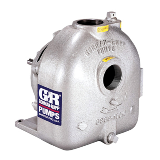
See Figure 1 for the approximate physical dimen some of the information such as mounting, line sions of this pump. OUTLINE DRAWING Figure 1. Pump Model 04B3-B PREINSTALLATION INSPECTION b. Check for and tighten loose attaching hard ware. Since gaskets tend to shrink after dry... -
Page 10: Positioning Pump
OM-01214 0 SERIES AND REPAIR section of this manual and per Mounting form duties as instructed. Locate the pump in an accessible place as close as practical to the liquid being pumped. Level mount e. If the pump and engine have been stored for ing is essential for proper operation. -
Page 11: Suction Lines
0 SERIES OM-01214 tapped, drill and tap the suction and discharge high suction lift, all connections in the suction line lines not less than 18 inches (457 mm) from the should be sealed with pipe dope to ensure an air suction and discharge ports and install the lines. -
Page 12: Discharge Lines
OM-01214 0 SERIES Figure 2. Recommended Minimum Suction Line Submergence vs. Velocity DISCHARGE LINES Siphoning If the application involves a high discharge head, gradually close the discharge throttling valve before stopping the pump. Do not terminate the discharge line at a level lower than that of the liquid being pumped unless a si... -
Page 13: Coupled Drives
0 SERIES OM-01214 Before checking alignment, tighten the foundation bolts. The pump casing feet and/or pedestal feet, and the driver mounting bolts should also be tightly secured. When checking alignment, disconnect the power source to ensure that the pump will remain inoperative. Figure 3B. -
Page 14: Drive Belt Tensioning
OM-01214 0 SERIES Tighten the belts in accordance with the belt manu Ideal drive belt tension is the lowest tension at facturer's instructions. If the belts are too loose, which the belt will not slip under peak load condi they will slip; if the belts are too tight, there will be tions. -
Page 15: Operation - Section C
OM-01214 0 SERIES OPERATION - SECTION C Review all SAFETY information in Section A. coming liquid to evacuate the air. After the pump and piping system have completely filled, evacu Follow the instructions on all tags, labels and ate any remaining air pockets in the pump or suc decals attached to the pump. -
Page 16: Operation
OM-01214 0 SERIES incorrect on a single‐phase motor, consult the liter Overheating can occur if operated with the valves ature supplied with the motor for specific instruc in the suction or discharge lines closed. Operating tions. against closed valves could bring the liquid to a boil, build pressure, and cause the pump to rup... -
Page 17: Stopping
OM-01214 0 SERIES Shut off the pump. The vacuum gauge reading will normal for bearings, and they can operate safely to immediately drop proportionate to static suction at least 180_F (82_C). lift, and should then stabilize. If the vacuum reading Checking bearing temperatures by hand is inaccu... -
Page 18: Troubleshooting - Section D
OM-01214 0 SERIES TROUBLESHOOTING - SECTION D Review all SAFETY information in Section A. Before attempting to open or service the pump: 1. Familiarize yourself with this manual. 2. Disconnect or lock out the power source to ensure that the pump will remain inoperative. - Page 19 OM-01214 0 SERIES TROUBLE POSSIBLE CAUSE PROBABLE REMEDY PUMP STOPS OR Suction intake not submerged at Check installation and correct FAILS TO DELIVER proper level or sump too small. submergence as needed. RATED FLOW OR Impeller or other wearing parts worn Replace worn or damaged parts.
-
Page 20: Preventive Maintenance
OM-01214 0 SERIES PREVENTIVE MAINTENANCE equipped) between regularly scheduled inspec tions can indicate problems that can be corrected Since pump applications are seldom identical, and before system damage or catastrophic failure oc pump wear is directly affected by such things as curs. - Page 21 PUMP MAINTENANCE AND REPAIR ‐ SECTION E MAINTENANCE AND REPAIR OF THE WEARING PARTS OF THE PUMP WILL MAINTAIN PEAK OPERATING PERFORMANCE. STANDARD PERFORMANCE FOR PUMP MODEL 04B3-B Based on 70_ F (21_ C) clear water at sea level Contact the Gorman‐Rupp Company to verify per...
- Page 22 Ï Ï Ï Ï Ï Ï Ï Ï Ï Ç Ç Ç Ç Ç Ç Ç Ç Î Î Î Î Î Î Î Î Î Î Î Î Figure 1. Pump Model 04B3-B PAGE E - 2 MAINTENANCE & REPAIR...
- Page 23 0 SERIES OM-01214 PARTS LIST Pump Model 04B3-B (From S/N 806819 Up) If your pump serial number is followed by an “N”, your pump is NOT a standard production model. Contact the Gorman‐Rupp Company to verify part numbers. ITEM PART NAME...
- Page 24 OM-01214 0 SERIES PUMP AND SEAL DISASSEMBLY AND REASSEMBLY Review all SAFETY information in Section A. Before attempting to open or service the pump: 1. Familiarize yourself with this man Follow the instructions on all tags, label and de ual. cals attached to the pump.
- Page 25 Use caution not to damage the pump cas ing bore when removing the wear ring. Impeller Removal Use Only Genuine Gorman-Rupp re Immobilize the impeller by inserting a bar between placement parts. Failure to do so may cre the impeller vanes, being careful not to damage ate a hazard and damage the pump or di...
- Page 26 OM-01214 0 SERIES chisel to complete the cuts through the ring, and strongly recommended that the bearings remove it from the seal plate. Use caution not to be replaced any time the shaft and bear damage the seal plate bore when removing the ings are removed.
- Page 27 0 SERIES OM-01214 cleaning solvent. Inspect the parts for wear or dam be cleaned and inspected in place. It is age as necessary. strongly recommended that the bearings be replaced any time the shaft and bear ings are removed. The bearings may be heated to ease installation. An induction heater, hot oil bath, electric oven, or Most cleaning solvents are toxic and hot plate may be used to heat the bearings.
- Page 28 OM-01214 0 SERIES Seal Reassembly and Installation shaft, never press or hit against the outer race, balls, or ball cage. Press only on the (Figures 1 and 3) inner race. Clean the seal cavity and shaft with a cloth soaked Install the gasket (6) and secure the bearing cap to in fresh cleaning solvent.
- Page 29 0 SERIES OM-01214 ROTATING RETAINER SPRING ELEMENT O‐RING STATIONARY SEAT IMPELLER IMPELLER SHAFT SHAFT SLEEVE IMPELLER ADJUSTING SHIMS SEAL PLATE BELLOWS Figure 3. Seal Assembly Carefully slide the assembled seal plate and sta tionary seal element over the shaft. Use caution not to nick or damage the stationary seat.
- Page 30 OM-01214 0 SERIES To verify the impeller positioning, measure the impeller location (dimension E). Add or remove im pump casing and impeller as shown in Figure 4. peller adjusting shims (16) until dimension E is ob Use these measurements to calculate the required tained.
- Page 31 0 SERIES OM-01214 Refer to OPERATION, Section C, before putting NOTE the pump back into service. The white reflector in the sight gauge must be posi tioned horizontally to provide proper drainage. LUBRICATION Under normal conditions, drain the bearing hous ing once each year and refill with clean oil.
- Page 32 For Warranty Information, Please Visit www.grpumps.com/warranty or call: U.S.: 419-755-1280 Canada: 519-631-2870 International: +1-419-755-1352 GORMAN‐RUPP PUMPS...
Need help?
Do you have a question about the 04B3-B and is the answer not in the manual?
Questions and answers