Table of Contents
Advertisement
Quick Links
BC
OM-01157-03
August 18, 1981
Rev. B 06‐05‐2013
INSTALLATION, OPERATION,
AND MAINTENANCE MANUAL
WITH PARTS LIST
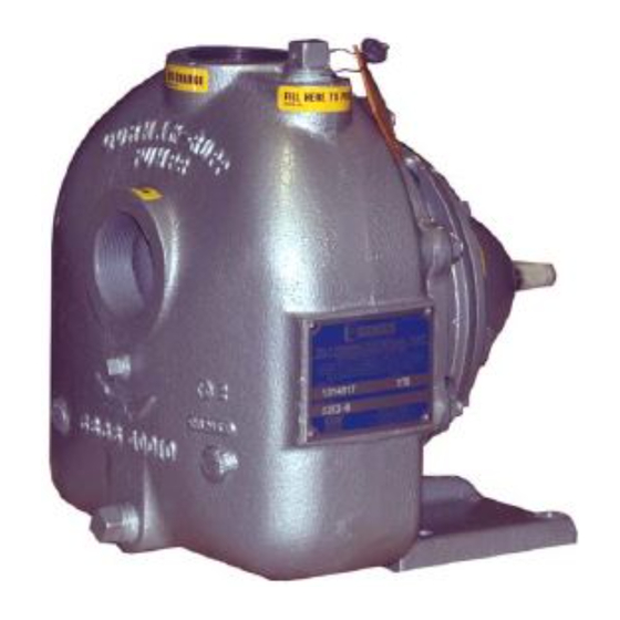
0 SERIES PUMP
MODEL
02K11-B
THE GORMAN‐RUPP COMPANY D MANSFIELD, OHIO
www.grpumps.com
D
GORMAN‐RUPP OF CANADA LIMITED
ST. THOMAS, ONTARIO, CANADA
Printed in U.S.A.
e
2009 The Gorman‐Rupp Company
Advertisement
Table of Contents

Related Manuals for GORMAN-RUPP 02K11-B


Summary of Contents for GORMAN-RUPP 02K11-B
- Page 1 August 18, 1981 Rev. B 06‐05‐2013 INSTALLATION, OPERATION, AND MAINTENANCE MANUAL WITH PARTS LIST 0 SERIES PUMP MODEL 02K11-B THE GORMAN‐RUPP COMPANY D MANSFIELD, OHIO www.grpumps.com GORMAN‐RUPP OF CANADA LIMITED ST. THOMAS, ONTARIO, CANADA Printed in U.S.A. 2009 The Gorman‐Rupp Company...
- Page 2 Register your new Gorman‐Rupp pump online at www.grpumps.com Valid serial number and e‐mail address required. RECORD YOUR PUMP MODEL AND SERIAL NUMBER Please record your pump model and serial number in the spaces provided below. Your Gorman‐Rupp distributor needs this information when you require parts or service. Pump Model: Serial Number:...
-
Page 3: Table Of Contents
TABLE OF CONTENTS INTRODUCTION ..........PAGE I - 1 SAFETY ‐... - Page 4 TABLE OF CONTENTS (continued) PUMP MAINTENANCE AND REPAIR ‐ SECTION E ....PAGE E - 1 STANDARD PERFORMANCE CURVE ........PAGE E - 1 PARTS LIST: Pump Model...
-
Page 5: Introduction
0 SERIES OM-01157 INTRODUCTION Thank You for purchasing a Gorman‐Rupp pump. The following are used to alert maintenance per Read this manual carefully to learn how to safely sonnel to procedures which require special atten install and operate your pump. Failure to do so tion, to those which could damage equipment, and could result in personal injury or damage to the to those which could be dangerous to personnel:... -
Page 6: Safety - Section A
0 SERIES OM-01157 SAFETY ‐ SECTION A This information applies to 0 Series ba sic pumps. Gorman‐Rupp has no con trol over or particular knowledge of the power source which will be used. Refer This pump is designed to handle petro to the manual accompanying the power leum products or other clean liquids source before attempting to begin oper... - Page 7 OM-01157 0 SERIES tional Electric Code and all local codes. If there is a conflict between the instruc tions in the manual accompanying the unit and the National Electric Code or Do not operate the pump against a the applicable local code, the National closed discharge valve for long periods or local code shall take precedence.
-
Page 8: Installation - Section B
See Figure 1 for the approximate physical dimen some of the information such as mounting, line sions of this pump. OUTLINE DRAWING Figure 1. Pump Model 02K11-B PREINSTALLATION INSPECTION b. Check for and tighten loose attaching hard ware. Since gaskets tend to shrink after dry... -
Page 9: Positioning Pump
OM-01157 0 SERIES AND REPAIR section of this manual and per The pump may have to be supported or shimmed form duties as instructed. to provide for level operation or to eliminate vibra tion. e. If the pump and engine have been stored for SUCTION AND DISCHARGE PIPING more than 12 months, some of the compo... -
Page 10: Suction Lines
0 SERIES OM-01157 ommendations when selecting and applying the SUCTION LINES pipe dope. The pipe dope should be compatible with the liquid being pumped. To avoid air pockets which could affect pump prim ing, the suction line must be as short and direct as Suction Lines In Sumps possible. -
Page 11: Discharge Lines
OM-01157 0 SERIES Figure 2. Recommended Minimum Suction Line Submergence vs. Velocity DISCHARGE LINES head, gradually close the discharge throttling valve before stopping the pump. Siphoning ALIGNMENT Do not terminate the discharge line at a level lower than that of the liquid being pumped unless a si The alignment of the pump and its power source is phon breaker is used in the line. -
Page 12: Coupled Drives
0 SERIES OM-01157 When checking alignment, disconnect the power source to ensure that the pump will remain inoperative. Figure 3B. Aligning Non‐Spider Type Couplings Adjusting the alignment in one direction Align non‐spider type couplings by using a feeler may alter the alignment in another direc gauge or taper gauge between the coupling halves tion. -
Page 13: Drive Belt Tensioning
OM-01157 0 SERIES Tighten the belts in accordance with the belt manu Ideal drive belt tension is the lowest tension at facturer's instructions. If the belts are too loose, which the belt will not slip under peak load condi they will slip; if the belts are too tight, there will be tions. -
Page 14: Operation - Section C
OM-01157 0 SERIES OPERATION - SECTION C Review all SAFETY information in Section A. coming liquid to evacuate the air. After the pump and piping system have completely filled, evacu Follow the instructions on all tags, labels and ate any remaining air pockets in the pump or suc decals attached to the pump. -
Page 15: Operation
OM-01157 0 SERIES ature supplied with the motor for specific instruc Overheating can occur if operated with the valves tions. in the suction or discharge lines closed. Operating against closed valves could bring the liquid to a boil, build pressure, and cause the pump to rup OPERATION ture or explode. -
Page 16: Stopping
OM-01157 0 SERIES Before checking for the source of the leak, check Checking bearing temperatures by hand is inaccu the point of installation of the vacuum gauge. rate. Bearing temperatures can be measured ac curately by placing a contact‐type thermometer against the housing. -
Page 17: Troubleshooting - Section D
OM-01157 0 SERIES TROUBLESHOOTING - SECTION D Review all SAFETY information in Section A. Before attempting to open or service the pump: 1. Familiarize yourself with this manual. 2. Disconnect or lock out the power source to ensure that the pump will remain inoperative. - Page 18 OM-01157 0 SERIES TROUBLE POSSIBLE CAUSE PROBABLE REMEDY PUMP STOPS OR Suction intake not submerged at Check installation and correct FAILS TO DELIVER proper level or sump too small. submergence as needed. RATED FLOW OR Impeller or other wearing parts worn Replace worn or damaged parts.
-
Page 19: Preventive Maintenance
OM-01157 0 SERIES PREVENTIVE MAINTENANCE equipped) between regularly scheduled inspec tions can indicate problems that can be corrected Since pump applications are seldom identical, and before system damage or catastrophic failure oc pump wear is directly affected by such things as curs. - Page 20 PUMP MAINTENANCE AND REPAIR ‐ SECTION E MAINTENANCE AND REPAIR OF THE WEARING PARTS OF THE PUMP WILL MAINTAIN PEAK OPERATING PERFORMANCE. STANDARD PERFORMANCE FOR PUMP MODEL 02K11-B Based on 70_ F (21_ C) clear water at sea level Contact the Gorman‐Rupp Company to verify per...
- Page 21 OM-01157 0 SERIES SECTION DRAWING PARTS PAGE Figure 1. 02K11-B Pump Model Assembly PAGE E - 2 MAINTENANCE & REPAIR...
- Page 22 0 SERIES OM-01157 PARTS LIST Pump Model 02K11-B (From S/N 740364 Up) If your pump serial number is followed by an “N”, your pump is NOT a standard production model. Contact the Gorman‐Rupp Company to verify part numbers. ITEM PART...
- Page 23 OM-01157 0 SERIES PUMP AND SEAL DISASSEMBLY 4. Check the temperature before opening any covers, plates, or AND REASSEMBLY plugs. 5. Close the suction and discharge Review all SAFETY information in Section A. valves. 6. Vent the pump slowly and cau Follow the instructions on all tags, label and de...
- Page 24 0 SERIES OM-01157 Impeller Removal Remove the hardware (9, 10 and 11) and slide the intermediate (22) and stationary portion of the seal Immobilize the impeller by wedging a block of off the shaft as a unit. Disengage the hardware (12 wood or a brass rod between the vanes.
- Page 25 OM-01157 0 SERIES be replaced any time the shaft and bear ings are removed. Clean the bearing housing, shaft and all compo To prevent damage during removal from nent parts (except the bearings) with a soft cloth the shaft, it is recommended that bearings soaked in cleaning solvent.
- Page 26 0 SERIES OM-01157 The seal is not normally reused because wear pat terns on the finished faces cannot be realigned during reassembly. This could result in premature failure. If necessary to reuse an old seal in an emer When installing the shaft and bearings into gency, carefully wash all metallic parts in fresh the bearing bore, push against the outer cleaning solvent and allow to dry thoroughly.
- Page 27 OM-01157 0 SERIES INTERMEDIATE SEAL CAP ROTATING RETAINER ELEMENT GASKETS DISC STATIONARY SEAT IMPELLER SHAFT IMPELLER SHIMS SNAP RING SEALING SPRING WEDGE Figure 3. Seal Assembly New seal assemblies may be equipped This seal is not designed for operation at with spring holding clips for storage temperatures above 160_F (71_C).
- Page 28 0 SERIES OM-01157 Impeller Installation To verify the impeller positioning, measure the vane plate and impeller as shown in Figure 4. Use Inspect the impeller and replace it if cracked or these measurements to calculate the required im badly worn. peller location (dimension E).
- Page 29 OM-01157 0 SERIES Bearings Power Source The bearings in this pump are lubricated from the Consult the literature supplied with the power manufacturer and permanently sealed. No addi source, or contact your local power source repre tional lubrication is required. sentative.
- Page 30 For U.S. and International Warranty Information, Please Visit www.grpumps.com/warranty or call: U.S.: 419-755-1280 International: +1-419-755-1352 For Canadian Warranty Information, Please Visit www.grcanada.com/warranty or call: 519-631-2870 THE GORMAN‐RUPP COMPANY D MANSFIELD, OHIO GORMAN‐RUPP OF CANADA LIMITED ST. THOMAS, ONTARIO, CANADA...
Need help?
Do you have a question about the 02K11-B and is the answer not in the manual?
Questions and answers