Table of Contents
Advertisement
Quick Links
BCE
OM‐01207‐04
February 1, 1985
Rev. B 09‐10‐2013
INSTALLATION, OPERATION,
AND MAINTENANCE MANUAL
WITH PARTS LIST
0 SERIES PUMP
MODEL
04A3-B
THE GORMAN‐RUPP COMPANY D MANSFIELD, OHIO
www.grpumps.com
D
GORMAN‐RUPP OF CANADA LIMITED
ST. THOMAS, ONTARIO, CANADA
Printed in U.S.A.
e
2009 The Gorman‐Rupp Company
Advertisement
Table of Contents

Related Manuals for GORMAN-RUPP 04A3-B


Summary of Contents for GORMAN-RUPP 04A3-B
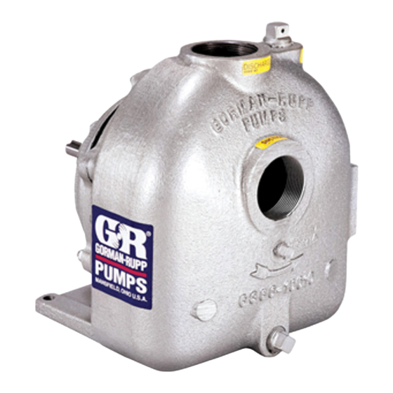
- Page 1 February 1, 1985 Rev. B 09‐10‐2013 INSTALLATION, OPERATION, AND MAINTENANCE MANUAL WITH PARTS LIST 0 SERIES PUMP MODEL 04A3-B THE GORMAN‐RUPP COMPANY D MANSFIELD, OHIO www.grpumps.com GORMAN‐RUPP OF CANADA LIMITED ST. THOMAS, ONTARIO, CANADA Printed in U.S.A. 2009 The Gorman‐Rupp Company...
- Page 2 Register your new Gorman‐Rupp pump online at www.grpumps.com Valid serial number and e‐mail address required. RECORD YOUR PUMP MODEL AND SERIAL NUMBER Please record your pump model and serial number in the spaces provided below. Your Gorman‐Rupp distributor needs this information when you require parts or service. Pump Model: Serial Number:...
-
Page 3: Table Of Contents
TABLE OF CONTENTS INTRODUCTION ..........PAGE I - 1 SAFETY ‐... - Page 4 TABLE OF CONTENTS (continued) PUMP MAINTENANCE AND REPAIR ‐ SECTION E ....PAGE E - 1 STANDARD PERFORMANCE CURVE ........PAGE E - 1 PARTS LIST: Pump End Assembly...
-
Page 5: Introduction
0 SERIES OM-01207 INTRODUCTION Thank You for purchasing a Gorman‐Rupp pump. The following are used to alert maintenance per Read this manual carefully to learn how to safely sonnel to procedures which require special atten install and operate your pump. Failure to do so tion, to those which could damage equipment, and could result in personal injury or damage to the to those which could be dangerous to personnel:... -
Page 6: Safety - Section A
0 SERIES OM-01207 SAFETY ‐ SECTION A This information applies to 0 Series ba sic pumps. Gorman‐Rupp has no con trol over or particular knowledge of the power source which will be used. Refer This pump is designed to handle petro to the manual accompanying the power leum products or other clean liquids source before attempting to begin oper... - Page 7 OM-01207 0 SERIES tional Electric Code and all local codes. If there is a conflict between the instruc tions in the manual accompanying the unit and the National Electric Code or Do not operate the pump without the the applicable local code, the National shields and/or guards in place over the or local code shall take precedence.
- Page 8 0 SERIES OM-01207 Never run this pump backwards. Be cer Pumps and related equipment must be in tain that rotation is correct before fully stalled and operated according to all na engaging the pump. tional, local and industry standards. SAFETY PAGE A - 3...
-
Page 9: Installation - Section B
See Figure 1 for the approximate physical dimen some of the information such as mounting, line sions of this pump. OUTLINE DRAWING Figure 1. Pump Model 04A3-B PREINSTALLATION INSPECTION b. Check for and tighten loose attaching hard ware. Since gaskets tend to shrink after dry... -
Page 10: Positioning Pump
OM-01207 0 SERIES AND REPAIR section of this manual and per Mounting form duties as instructed. Locate the pump in an accessible place as close as practical to the liquid being pumped. Level mount e. If the pump and engine have been stored for ing is essential for proper operation. -
Page 11: Suction Lines
0 SERIES OM-01207 tapped, drill and tap the suction and discharge high suction lift, all connections in the suction line lines not less than 18 inches (457 mm) from the should be sealed with pipe dope to ensure an air suction and discharge ports and install the lines. -
Page 12: Discharge Lines
OM-01207 0 SERIES Figure 2. Recommended Minimum Suction Line Submergence vs. Velocity DISCHARGE LINES head, gradually close the discharge throttling valve before stopping the pump. Siphoning ALIGNMENT Do not terminate the discharge line at a level lower than that of the liquid being pumped unless a si The alignment of the pump and its power source is phon breaker is used in the line. -
Page 13: Coupled Drives
0 SERIES OM-01207 When checking alignment, disconnect the power source to ensure that the pump will remain inoperative. Figure 3B. Aligning Non‐Spider Type Couplings Adjusting the alignment in one direction Align non‐spider type couplings by using a feeler may alter the alignment in another direc gauge or taper gauge between the coupling halves tion. -
Page 14: Drive Belt Tensioning
OM-01207 0 SERIES Tighten the belts in accordance with the belt manu Ideal drive belt tension is the lowest tension at facturer's instructions. If the belts are too loose, which the belt will not slip under peak load condi they will slip; if the belts are too tight, there will be tions. -
Page 15: Operation - Section C
OM-01207 0 SERIES OPERATION - SECTION C Review all SAFETY information in Section A. coming liquid to evacuate the air. After the pump and piping system have completely filled, evacu Follow the instructions on all tags, labels and ate any remaining air pockets in the pump or suc decals attached to the pump. -
Page 16: Operation
OM-01207 0 SERIES incorrect on a single‐phase motor, consult the liter Overheating can occur if operated with the valves ature supplied with the motor for specific instruc in the suction or discharge lines closed. Operating tions. against closed valves could bring the liquid to a boil, build pressure, and cause the pump to rup... -
Page 17: Stopping
OM-01207 0 SERIES Shut off the pump. The vacuum gauge reading will normal for bearings, and they can operate safely to immediately drop proportionate to static suction at least 180_F (82_C). lift, and should then stabilize. If the vacuum reading Checking bearing temperatures by hand is inaccu... -
Page 18: Troubleshooting - Section D
OM-01207 0 SERIES TROUBLESHOOTING - SECTION D Review all SAFETY information in Section A. Before attempting to open or service the pump: 1. Familiarize yourself with this manual. 2. Disconnect or lock out the power source to ensure that the pump will remain inoperative. - Page 19 OM-01207 0 SERIES TROUBLE POSSIBLE CAUSE PROBABLE REMEDY PUMP STOPS OR Suction intake not submerged at Check installation and correct FAILS TO DELIVER proper level or sump too small. submergence as needed. RATED FLOW OR Impeller or other wearing parts worn Replace worn or damaged parts.
-
Page 20: Preventive Maintenance
OM-01207 0 SERIES PREVENTIVE MAINTENANCE equipped) between regularly scheduled inspec tions can indicate problems that can be corrected Since pump applications are seldom identical, and before system damage or catastrophic failure oc pump wear is directly affected by such things as curs. - Page 21 PUMP MAINTENANCE AND REPAIR ‐ SECTION E MAINTENANCE AND REPAIR OF THE WEARING PARTS OF THE PUMP WILL MAINTAIN PEAK OPERATING PERFORMANCE. STANDARD PERFORMANCE FOR PUMP MODEL 04A3-B Based on 70_F (21_C) clear water at sea level Contact the Gorman‐Rupp Company to verify per...
- Page 22 OM-01207 0 SERIES PARTS PAGE SECTION DRAWING Figure 1. Pump Model 04A3-B PAGE E - 2 MAINTENANCE & REPAIR...
- Page 23 0 SERIES OM-01207 PARTS LIST Pump Model 04A3-B (From S/N 818101 Up) If your pump serial number is followed by an “N”, your pump is NOT a standard production model. Contact the Gorman‐Rupp Company to verify part numbers. ITEM PART NAME...
- Page 24 OM-01207 0 SERIES PUMP AND SEAL DISASSEMBLY 4. Check the temperature before opening any covers, plates, or AND REASSEMBLY plugs. 5. Close the suction and discharge Review all SAFETY information in Section A. valves. Follow the instructions on all tags, label and de 6.
- Page 25 0 SERIES OM-01207 separate the pump casing and gasket (36) from the seal plate and pedestal. Tie and tag any leveling shims used under the cas Use caution not to damage the seal plate ing feet to ease reassembly. bore when removing the wear ring. Inspect the wear ring (42) for excessive wear or Remove the machine screws (48) and slide the scoring.
- Page 26 OM-01207 0 SERIES a pair of screwdrivers against the heads of the ma races and cause premature bearing fail chine screws. After removing the retainer, tighten ure. the machines screws in the retainer. Rotate the bearings by hand to check for rough ness or binding and inspect the bearing balls.
- Page 27 0 SERIES OM-01207 oil seal into the bearing cap until the face is just NOTE flush with the outer surface of the bearing cap. If a hot oil bath is used to heat the bearings, both the oil and the container must be absolutely clean. If Install the O‐ring (31) and secure the bearing cap the oil has been previously used, it must be thor...
- Page 28 OM-01207 0 SERIES failure. If necessary to reuse an old seal in an emer age. If any components are worn, replace the com gency, carefully wash all metallic parts in fresh plete seal; never mix old and new seal parts. cleaning solvent and allow to dry thoroughly.
- Page 29 0 SERIES OM-01207 Subassemble the O‐ring onto the stationary seat faces contact. Continue to push the sleeve through and lubricate it with water or light oil. Use even the seal until it is fully seated against the shaft pressure to press the stationary portion of the seal shoulder.
- Page 30 OM-01207 0 SERIES Install the casing gasket (36) and secure the cas Bearings ing to the seal plate and pedestal with the nuts (35). Reinstall any leveling shims under the casing mounting feet, and secure the casing to the base The pedestal was fully lubricated when shipped with the previously removed hardware.
- Page 31 For U.S. and International Warranty Information, Please Visit www.grpumps.com/warranty or call: U.S.: 419-755-1280 International: +1-419-755-1352 For Canadian Warranty Information, Please Visit www.grcanada.com/warranty or call: 519-631-2870 THE GORMAN‐RUPP COMPANY D MANSFIELD, OHIO GORMAN‐RUPP OF CANADA LIMITED ST. THOMAS, ONTARIO, CANADA...
Need help?
Do you have a question about the 04A3-B and is the answer not in the manual?
Questions and answers