Metal Work EB 80 User Manual
Ethernet/ip
Hide thumbs
Also See for EB 80:
- User manual (62 pages) ,
- Assembly instructions manual (8 pages) ,
- User manual (34 pages)
Table of Contents
Advertisement
Available languages
Available languages
Advertisement
Table of Contents

Related Manuals for Metal Work EB 80


Summary of Contents for Metal Work EB 80
- Page 1 MANUALE D'USO EtherNet/IP USER MANUAL EtherNet/IP...
-
Page 2: Table Of Contents
1.5.1 Impiego di switch PAG. 2. MESSA IN SERVIZIO PAG. 2.1 CONNESSIONI AL SISTEMA EB 80 EtherNet/IP PAG. 2.2 INSTALLAZIONE DEL SISTEMA EB 80 IN UNA RETE EtherNet/IP PAG. 2.2.1 File di configurazione EDS PAG. 2.2.2 Configurazione di un Generic Adapter PAG. - Page 3 4.2 DIAGNOSTICA DEL SISTEMA EB 80 – CONNESSIONE ELETTRICA PAG. 26 4.3 DIAGNOSTICA DEL SISTEMA EB 80 – BASE VALVOLE PAG. 28 4.4 DIAGNOSTICA DEL SISTEMA EB 80 – MODULI SEGNALI - S PAG. 28 4.4.1 Diagnostica dei Moduli segnali - S – Input Digitali PAG. 28 4.4.2 Diagnostica dei Moduli segnali - S –...
-
Page 4: Impiego Ammesso
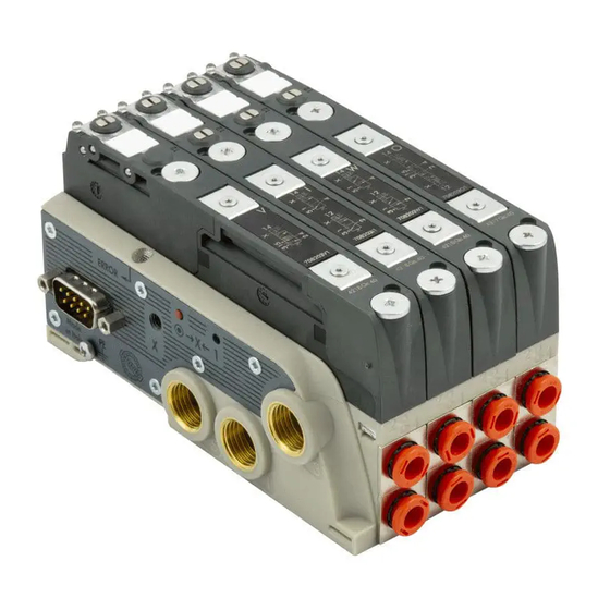
IMPIEGO AMMESSO La Connessione Elettrica EtherNet/IP consente il collegamento del sistema EB 80 ad una rete EtherNet/IP. Conforme alle specifiche ODVA offre funzioni di diagnostica ed è disponibile nella configurazione fino a 128 Out per elettro piloti, 128 out digitali, 128 Input digitali, 16 out analogici, 16 input analogici e 16 input analogici per temperatura. -
Page 5: Connettore M12 Per La Connessione Alla Rete Ethernet/Ip
Per una corretta comunicazione, utilizzare esclusivamente cavi a norma EtherNet/IP Cat.5 /Classe D 100 MHz come quello proposto nel catalogo Metal Work. Errori di installazione possono dare luogo a errori di trasmissione con conseguenti malfunzionamenti dei dispositivi. Le cause più frequenti di malfunzionamenti dovuti alla trasmissione dati difettosa sono: •... -
Page 6: Corrente Assorbita
Vedere https://www.odva.org 1.5.1 Impiego di switch La connessione elettrica EB 80 EtherNet/IP è dotata di uno switch integrato a due porte, che consente la realizzazione di reti lineari. La rete può essere suddivisa in ulteriori segmenti, utilizzando degli switch supplementari. -
Page 7: Messa In Servizio
DHCP Server. Impostando nuovamente su 00 i due rotary switch, viene ripristinato l'indirizzo di fabbrica. La corretta comunicazione tra il Master e il sistema EB 80 collegato avviene soltanto se a quest’ultimo è stato assegnato lo stesso indirizzo IP specificato nella configurazione del Master. -
Page 8: Configurazione Del Sistema Eb
Led del sistema, basi valvole, moduli di segnale ed isole addizionali. Il sistema EB 80 è caratterizzato da un'elevata flessibilità. È sempre possibile modificare la configurazione aggiungendo, togliendo o modificando le basi per valvole, moduli di segnale o isole addizionali. -
Page 9: Configurazione Del Sistema Eb 80 In Una Rete Ethernet/Ip
Selezionare dal catalogo hardware del sistema di sviluppo, il modulo EB 80 EtherNet/IP, inserirlo nella configurazione e assegnarlo al Master. Al dispositivo vengono assegnati tutti i bytes di uscita e tutti i bytes di ingresso, compreso il byte di stato che indica lo stato diagnostico del sistema EB 80. -
Page 10: Parametri All'avvio - Param 12 System Start
2.5.3.4 Abilitazione diagnostica I4.0 - Param 15 I4.0 enable Consente di abilitare le funzioni diagnostiche I4.0. Per la descrizione completa delle fuzioni vedere il manuale "EB 80 manuale d'uso delle funzioni 4.0 EtherNet/IP". 2.5.3.5 Tempo aggiornamento dati valvole - Param 16 valves data refresh time (ms) 2.5.3.6 Tempo aggiornamento attuatori - Param 17 Actuators data refresh time (ms) - Page 11 Esempio: Parameter Parameter Name Parameter Value Object 1: Type 04 Analog Inputs 02282S04 Parameter type User Value Object ID Par1 CH1: Ampiezza del segnale Par2 CH1: Filtro valore misurato Par3 CH1: Fondo scala utente (MSB) Par4 CH1: Fondo scala utente (LSB) Par5 CH2: Ampiezza del segnale Par6...
-
Page 12: Accessori
Terminale di chiusura con rimando La connessione elettrica Addizionale - E permette di collegare ad un unico nodo EtherNet/IP diversi sistemi EB 80. Per fare questo l’isola principale deve essere dotata di un terminale cieco tipo C3, dotato di un connettore M8. -
Page 13: Indirizzamento Della Connessione Elettrica Addizionale - E0Ad
3.3 MODULI DI SEGNALI - S I sistemi EB 80 sono corredati da numerosi moduli di gestione dei segnali di ingresso o uscita. Possono essere inseriti sia in sistemi con connessione elettrica EtherNet/IP che in sistemi con connessione elettrica Addizionale. -
Page 14: Stato Di Attivazione
3.3.1.4 Stato di attivazione È possibile selezionare lo stato di attivazione di ogni singolo ingresso. • Valore = 0 Normalmente Aperto, il segnale è attivo quando il sensore è attivo. Il Led è attivo quando il sensore è attivo. • Valore = 1 Normalmente Chiuso, il segnale è attivo quando il sensore è disattivo. Il Led è attivo quando il sensore è disattivo. Esempio di configurazione del primo Modulo S collegato, con 8 ingressi NC: Stato di attivazione modulo 1 = 255 Esempio di configurazione del terzo Modulo S collegato, con 4 ingressi X1…X4 NC e 4 ingressi X5…X8 NO: Stato di attivazione modulo 3 = 240... -
Page 15: Modulo Output Digitali
Esempio di configurazione: Filtro di input Stato di attivazione Bit 7 Bit 6 Bit 5 Bit 4 Bit 3 Bit 2 Bit 1 Bit 0 Bit 7 Bit 6 Bit 5 Bit 4 Bit 3 Bit 2 Bit 1 Bit 0 IN 8 IN 7 IN 6... -
Page 16: Stato Di Sicurezza - Fail Safe
3.3.2.5 Stato di sicurezza - Fail Safe Questa funzione consente di definire lo stato delle uscite nel caso di comunicazione interrotta con il Master. • Valore = 0 Hold Last State, l’elettropilota mantiene lo stato in cui si trovava prima dell’interruzione della comunicazione con il Master. •... -
Page 17: Modulo 6 Output Digitali M8 + Alimentazione Elettrica
3.3.3 Modulo 6 Output digitali M8 + alimentazione elettrica Ogni modulo può gestire fino a 6 uscite digitali, è configurabile esattamente come il Modulo 8 Output digitali M8 utilizzando l'oggetto N°1 ÷ N°9 06 Digital Outputs 02282S03. Dispone di un connettore per l’alimentazione ausiliaria, che consente di aumentare la corrente fornibile dal modulo e dal sistema.Deve essere inserito nel sistema, quando vengono installati più... -
Page 18: Modulo 4 Input Analogici M8
3.3.4 Modulo 4 Input analogici M8 Ogni modulo può gestire fino a 4 ingressi analogici liberamente configurabili sia in tensione che in corrente. Ogni ingresso è definito con 2 byte, iniziando dal byte In 17. Converte i segnali con una risoluzione di 15 bit più il segno, i valori numerici disponibili al sistema di controllo, sono compresi tra –32768 e +32767. -
Page 19: Fondo Scala Utente
3.3.4.4 Fondo Scala utente L’impostazione di questo valore consente di modificare la scala dei valori numerici inviati al sistema di controllo in funzione del valore del segnale analogico. Deve essere abilitato impostando “Linear scaled” nel Parametro 14. Ogni input è definito con 2 Byte. Consente di impostare valori fino a 27531 per i canali in tensione e 27566 per i canali in corrente. -
Page 20: Modulo 4 Output Analogici M8
3.3.5 Modulo 4 Output analogici M8 Ogni modulo può gestire fino a 4 uscite analogiche liberamente configurabili sia in tensione che in corrente. Ogni uscita è definita con 2 byte, iniziando dal byte Out 54. Converte i segnali con una risoluzione di 15 bit più il segno, i valori numerici impostabili nel sistema di controllo, sono compresi tra –32768 e +32767. -
Page 21: Fault Mode Value
3.3.5.8 Fault mode value Questa funzione consente di definire singolarmente il valore del segnale analogico di uscita nel caso di comunicazione interrotta con il Master. Ogni uscita è definita con 2 Byte. Esempio: come tabella 3.3.5.3 Fondo Scala utente Oggetto: N°1 04 Analog Outputs 02282S05 Parametro Funzione Valore di default Default... -
Page 22: Modulo 4 Input Analogici M8 Per La Misura Di Temperature
3.3.6 Modulo 4 input analogici M8 per la misura di Temperature Ogni modulo S per la misura di temperature può gestire fino a 4 ingressi, liberamente configurabili per l’utilizzo di sensori di temperatura o di termocoppie di vario tipo. Dispongono di alcuni parametri configurabili singolarmente. La compensazione della temperatura (Cold Junction Compensation CJC) per l’utilizzo delle termocoppie è... -
Page 23: Parametri Dell'unità
3.3.6.3 Parametri dell’unità Parametri comuni • Unità di misura: è possibile configurare la temperatura letta in °Celsius oppure in °Fahrenheit 0 = °Celsius 1 = °Fahrenheit • Soppressione del rumore: consente di sopprimere il rumore elettrico generato dalla rete di alimentazione. Lavora in combinazione con il parametro “Filtro di acquisizione”. -
Page 24: Valore Minimo
3.3.6.4 Valore Minimo Valore di riferimento per monitor valore minimo. 3.3.6.5 Valore Massimo Valore di riferimento per monitor valore massimo. 3.3.6.6 Configurazione parametri Oggetto: N°1 04 Temperature Inputs 02282S08 Parametro Funzione Valore di default Default Par1 Unità di misura (0) °C Par2 Soppressione rumore (0) -
Page 25: Funzioni I4.0
Par18 Tempo ritorno (Byte3) 0 ms Par19 Tempo ritorno (Byte2) 0 ms Par20 Tempo ritorno (Byte1) 0 ms Par21 Tolleranza Tempo ritorno (1...15) N.B.: Per una descrizione completa delle funzioni vedere "EB 80 manuale d'uso delle funzioni Industry 4.0 EtherNet/IP". -
Page 26: Diagnostica
La diagnostica sistema EB 80 - Connessione elettrica - è definita dallo stato dei Led Power, Bus Error e Local Error. Le funzioni di diagnostica del sistema EB 80, restituiscono al controllore, in ordine di priorità, lo stato del sistema tramite dei codici di errore in formato esadecimale o binario. - Page 27 Piastra di chiusura lato moduli La rete EB 80 Net non è inserire il connettore di terminazione. S non connessa. correttamente terminata ON (verde) ROSSO...
-
Page 28: Diagnostica Del Sistema Eb 80 - Base Valvole
Led della base) 4.4 DIAGNOSTICA DEL SISTEMA EB 80 – MODULI SEGNALI - S La diagnostica dei Moduli di segnali - S è definita dallo stato dei Led di interfaccia. La generazione di un allarme attiva un messaggio software per la Connessione Elettrica con il codice relativo all’errore rilevato. -
Page 29: Diagnostica Dei Moduli Segnali - S - Input Analogici
4.4.3 Diagnostica dei Moduli segnali - S – Input Analogici Significato Soluzione X1..X4 L’ingresso non è attivo ON (verde) L’ingresso è attivo e funziona correttamente VERDE Segnale analogico fuori dal range ammesso Impostare correttamente il tipo di ingresso Sostituire il sensore con uno di tipo ammesso (lampeggiante) ON (rosso) -
Page 30: Diagnostica Dei Moduli Segnali - S - Ingressi Analogici Per Misura Di Temperature
La rete EB 80 può essere configurata componendo le isole secondo le esigenze dell’impianto. Per un funzionamento sicuro ed affidabile, è comunque necessario rispettare dei limiti, imposti dal sistema di trasmissione seriale basato sulla tecnologia CAN e utilzzare i cavi schermati, twistati e con impedenza controllata, forniti da Metal Work. L’insieme formato da: •... -
Page 31: Dati Tecnici
6. DATI TECNICI 6.1 CONNESSIONE ELETTRICA EtherNet/IP DATI TECNICI Fieldbus 10 - 100 Mbit/S - Full-duplex - Half-duplex - Supporta l’Autonegoziazione e il Quick Connect Impostazioni di fabbrica Indirizzo IP: 192.168.193.32 Indirizzamento Software - DHCP hardware Range di tensione di alimentazione 12 -10% 24 +30% Tensione minima di funzionamento... -
Page 32: Moduli Di Segnali - S - Output Digitali + Alimentazione Elettrica
6.4 MODULI DI SEGNALI - S - OUTPUT DIGITALI + ALIMENTAZIONE ELETTRICA DATI TECNICI 6 Output digitali M8 + Alimentazione elettrica Range di tensione di alimentazione 12 -10% 24 +30% Tensione minima di funzionamento 10.8 Tensione massima di funzionamento 31.2 Tensione massima ammissibile Tensione in uscita Corrispondente alla tensione di alimentazione... -
Page 33: Moduli Di Segnali - S - Input Analogici Per La Misura Di Temperature
6.7 MODULI DI SEGNALI - S - INPUT ANALOGICI PER LA MISURA DI TEMPERATURE DATI TECNICI 4 Input analogici M8 per la misura di temperature Tensione di alimentazione sensori Corrispondente alla tensione di alimentazione Tensione massima di ingresso Tipo di sensore (RTD) al platino (-200 ÷... - Page 34 PAGE 38 2. COMMISSIONING PAGE 39 2.1 CONNECTIONS TO THE EB 80 EtherNet/IP SYSTEM PAGE 39 2.2 INSTALLATION OF THE EB 80 SYSTEM IN A EtherNet/IP NETWORK PAGE 39 2.2.1 EDS configuration file PAGE 39 2.2.2 Generic Adapter configuration PAGE 39 2.2.3 IP Address assignment...
- Page 35 4.2 EB 80 SYSTEM DIAGNOSTIC MODE – ELECTRICAL CONNECTION PAGE 58 4.3 EB 80 SYSTEM DIAGNOSTIC MODE – VALVE BASE PAGE 60 4.4 EB 80 SYSTEM DIAGNOSTIC MODE – SIGNAL MODULES - S PAGE 60 4.4.1 Diagnostic mode of Signal Modules - S – Digital Inputs PAGE 60 4.4.2 Diagnostic mode of Signal Modules - S –...
- Page 36 INTENDED USE The EtherNet/IP Electrical Connection can be used to connect the EB 80 system to a EtherNet/IP network. In compliance with current specifications, the ODVA offers diagnostic functions and is available in the configuration up to 128 outputs for solenoid pilots, 128 digital outputs, 128 digital inputs, 16 analogue outputs, 16 analogue inputs and 16 analogue inputs for temperatures.
- Page 37 • 0240005093 / 095 /100100100 - Straight M12 D-coded connector for bus with cable. WARNING For correct communication, only use EtherNet/IP cables, cat. 5 / Class D 100MHz of the type shown in the Metal Work catalogue. Incorrect installation can cause transmission errors and lead to malfunction of the devices.
- Page 38 1.5.1 Use of Switches EB 80 EtherNet/IP electrical connection comes with an integrated two-port switch to be used for the installation of linear networks. The network can be divided into several segments, using additional switches. Make sure that the devices used comply with Industrial Ethernet specifications and support all EtherNet/IP functions.
- Page 39 By setting the two rotary switches back to 00, the factory address is restored. Correct communication between the Master and the EB 80 system only occurs if at this system it has been assigned the same IP address specified in...
- Page 40 - press button "A" and reconnect the M8 power connector, by holding it down until all the indicator lights on the system, valve bases, signal modules and additional islands temporarily flash. The EB 80 system is highly flexible and its configuration can be changed at any time by adding, removing or altering the bases for valves, signal modules or additional islands.
- Page 41 2.5 CONFIGURING THE EB 80 SYSTEM IN EtherNet/IP NETWORK Select the header module EB 80 EtherNet/IP from the hardware catalogue of the development system, add it to the configuration and assign it to the Master. All the output and the input bytes, including the byte indicating the EB 80 system diagnostic state, are assigned to the device.
- Page 42 2.5.3.4 Enable of I4.0 diagnostic - Param 15 I4.0 enable It allows to enabled the I4.0 diagnostic functions. For a complete description of the functions, see the "EB 80 USER MANUAL of Industry 4.0 EtherNet/IP functions". 2.5.3.5 Valves data refresh time - Param 16 valves data refresh time (ms) 2.5.3.6 Actuators data refresh time - Param 17 Actuators data refresh time (ms)
- Page 43 Example: Parameter Parameter Name Parameter Value Object 1: Type 04 Analog Inputs 02282S04 Parameter type User Value Object ID Par1 CH1: Signal range Par2 CH1: Filtering the value measuredo Par3 CH1: User full scale (MSB) Par4 CH1: User full scale (LSB) Par5 CH2: Signal range Par6...
- Page 44 The connection of multiple systems requires all the additional islands to be equipped with C3 blind end plates, 1 = CAN H except for the last one that must be fitted with a C2 blind end plate with an EB 80 Net serial line termination 2 = CAN L connector.
- Page 45 The digital input module makes it possible to read digital inputs with a maximum signal exchange frequency of 1kHz. High-frequency reading is possible for all inputs, with up to a maximum of 2 modules connected to the EB 80 network.
- Page 46 3.3.1.4 Operating state The polarity of each input can be selected as follows. • Value = 0 Normally Open, the signal is ON when the sensor is enabled. The LED light is on when the sensor is enabled. • Value = 1 ormally Closed, the signal is ON when the sensor is disabled. The LED light is on when the sensor is disabled. Example of configuration of the first connected S module, with 8 NC inputs: Activation Status Module 1 = 255 Example of configuration of the third connected S module, with 4 inputs X1…X4 NC and 4 inputs X5…X8 NO: Activation Status Module 3 = 240...
- Page 47 Example of configuration: Input filter Operating state Bit 7 Bit 6 Bit 5 Bit 4 Bit 3 Bit 2 Bit 1 Bit 0 Bit 7 Bit 6 Bit 5 Bit 4 Bit 3 Bit 2 Bit 1 Bit 0 IN 8 IN 7 IN 6 IN 5...
- Page 48 3.3.2.5 Fail safe outputs This function can be used to determine the output state when communication with the Master is interrupted. • Value = 0 Hold Last State, the solenoid pilot remains at the state it found itself before communication with the Master was interrupted. •...
- Page 49 3.3.3 Digital 6-Output M8 Module + electrical power supply Each module can handle up to 6 digital outputs and can be configured just like the M8 8 digital output module, using the object No.1 - No.9 06 Digital Outputs 02282S03. It comes with a connector for auxiliary power supply, which makes it possible to increase the current supplied by the module and system.
- Page 50 3.3.4 Analogue 4-Input M8 Module Each module can handle up to 4 analogue inputs with freely configurable voltage and current. Each input is defined by 2 bytes, starting from byte In 17. This module converts signals with a resolution of 15 bits plus the sign. The numerical values available to the control system are between –32768 and +32767.
- Page 51 3.3.4.4 User full scale This value can be set to change the scale of numerical values sent to the control system as a function of the analogue signal value. It must be enabled by setting “Linear scaled” in Parameter 14. Each input is defined by 2 bytes. Makes it possible to set values up to 27531 for voltage channels and 27566 for current channels.
- Page 52 3.3.5 Analogue 4-Output M8 Module Each module can handle up to 4 analogue outputs with freely configurable voltage and current. Each output is defined with 2 bytes, starting from byte Out 54. This module converts signals with a resolution of 15 bits plus the sign. The numerical values settable in the control system are between –32768 and +32767..
- Page 53 3.3.5.8 Fault mode value This function can be used to determine the value of the analogue output signal when communication with the Master is interrupted. Each output is defined with 2 bytes. Example: same as in table 3.3.5.3 User Full Scale Object: No.1 04 Analog Outputs 02282S05 Parameter Function Default value...
- Page 54 3.3.6 M8 analogue 4-input module for temperature measurement Each temperature measurement module S can handle up to 4 inputs that can be configured freely for the use of temperature sensors or thermocouples of various type. They come with some individually configurable parameters. Temperature compensation (CJC –...
- Page 55 3.3.6.3 Unit Parameters Common parameters • Unit of measurement: it is possible to configure the temperature reading °Celsius or °Fahrenheit 0 = °Celsius 1 = °Fahrenheit • Noise suppression: suppresses electrical noise generated by mains electricity supply. This parameter works in conjunction with the "Acquisition Filter"...
- Page 56 3.3.6.4 Minimum value Reference value for monitor minimum value. 3.3.6.5 Maximum value Reference value for monitor maximum value. 3.3.6.6 Parameters configuration Object: No.1 04 Temperature Inputs 02282S08 Parameter Function Default value Default Par1 Unit of measurement (0) °C Par2 Noise suppression (0) 50 Hz Par3 CH1: Type of sensor (0)
- Page 57 Par19 Actuator return time (Byte2) 0 ms Par20 Actuator return time (Byte1) 0 ms Par21 Tolerance of actuator return time (1...15) N.B.: For a complete description of the functions, see the "EB 80 USER MANUAL of Industry 4.0 EtherNet/IP functions".
- Page 58 4. DIAGNOSTICS The diagnosis of the EB 80 EtherNet/IP system is defined by the state of the interface LED lights. Each component in the system relays its state, locally by LED lights, and to the EtherNet/IP node by software messages.
- Page 59 Turn off power supply, install the closing flashing) number. plate using the terminal board provided or insert the termination connector. Closing plate on S modules not The EB 80 Net network not connected. properly completed. ON (green) 0x06 Addressing error: Connect the valve bases or the signal •...
- Page 60 4.4 EB 80 SYSTEM DIAGNOSTIC MODE – SIGNAL MODULES - S The diagnosis of Signal Modules - S is defined by the state of the interface Led lights. The generation of an alarm activates a software electrical connection message with the code associated with the detected error.
- Page 61 4.4.3 Diagnostic mode of Signal Modules - S – Analogue Inputs Meaning Solution X1..X4 Input not active ON (green) The input is active and works properly GREEN Analogue signal outside permitted range Set input type correctly Replace sensor with a permitted type (flashing) ON (red)
- Page 62 5. CONFIGURATION LIMITS The EB 80 network can be configured by assembling the islands according to the requirements of the system in which it is mounted. For the system to operate safely and reliably, it is important to keep to the constraints associated with the serial transmission system based on CAN technology and use shielded, twisted cables with controlled impedance, supplied by Metal Work.
- Page 63 6. TECHNICAL DATA 6.1 EtherNet/IP ELECTRICAL CONNECTION TECHNICAL DATA Fieldbus 10 - 100 Mbit/S - Full-duplex - Half-duplex - Supports auto-negotiation and Quick Connect Factory settings IP address: 192.168.193.32 Addressing Software - DHCP hardware Supply voltage range 12 -10% 24 +30% Minimum operating voltage 10.8 Maximum operating voltage...
- Page 64 6.4 SIGNAL MODULES - S - DIGITAL OUTPUTS + ELECTRICAL POWER SUPPLY TECHNICAL DATA 6 M8 Digital Outputs + Electrical power supply Supply voltage range 12 -10% 24 +30% Minimum operating voltage 10.8 Maximum operating voltage 31.2 Maximum admissible voltage Output voltage Corresponding to power voltage Current for each connector...
- Page 65 6.7 SIGNAL MODULES - S - ANALOGUE INPUTS FOR TEMPERATURE MEASUREMENT TECHNICAL DATA 4 M8 analogue Inputs for temperature measurement Sensors supply voltage Corresponding to the supply voltage Maximum input voltage Sensor type (RTD) platinum (-200 to +850°C) Pt100, Pt200, Pt500, Pt1000 (TK = 0.00385 and TK = 0.00391) nichel (-60 to +180°C) Ni100, Ni120, Ni500, Ni1000 (TK = 0.00618) Connections type (RTD)
Need help?
Do you have a question about the EB 80 and is the answer not in the manual?
Questions and answers