Advertisement
Quick Links
HEAVY DUTY MULTIMACH INSTRUKCJA MONTAŻU
HEAVY DUTY MULTIMACH USER MANUAL
MONTAŻ I TESTY PNEUMATYCZNE
Ustawić wszystkie zawory w żądanej
kolejności. Podczas montażu należy zwrócić
uwagę na wypusty pozycjonujące „A" , tak
aby zostały umieszczone w odpowiednich
gniazdach osadczych w poprzedzających
modułach. Dodatkowo należy zwrócić uwagę
na prawidłowe osadzenie uszczelnień „B"
w odpowiednich rowkach. Na płaskiej
powierzchni umieszczamy płytę końcową
a następnie kolejno układamy pozostałe
moduły. Po ułożeniu wszystkich modułów
dociskamy od strony płyty zasilającej całą
wyspę – tak aby zapewnić poprawny montaż.
Po dociśnięciu wyspy, dokręcić tylni (dłuższy)
wkręt dociskowy kluczem imbusowym CH 2,5
z momentem 2 Nm.
Dokręcić znajdujący się po przeciwnej stronie
(krótszy) wkręt dociskowy kluczem
imbusowym CH2.5 z momentem 2 Nm.
Wykonać tę samą procedurę dla wszystkich
modułów w wyspie.
Po montażu wyspy zaworowej należy
przeprowadzić test pneumatyczny aby
sprawdzić jej szczelność. Przed podaniem
ciśnienia należy zaślepić wszystkie wyjścia
zaworów (ryzyko uszkodzenia uszczelnień w
skutek gwałtownego przepływu powietrza).
Ciśnienie zasilające należy podłączyć w
oznaczone przyłącza wtykowe 1, 11, X.
Wartość ciśnienia zasilającego musi zawsze
znajdować się między dwoma wartościami
granicznymi wskazanymi przy przyłączach
wtykowych.
ASSEMBLY AND PNEUMATIC TESTING
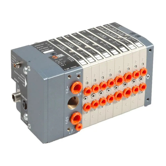
Position the valves in the desired sequence,
making sure the small teeth "A" of each guard
engage with the next one and in the seat of
the blind terminal.
Also check that gasket "B" rests in its seat.
Place the blind terminal on a fl at surface.
Apply a thrust of several kilograms on the
input terminal to compact the valves properly
one against the other.
Tighten the rear locking grub screw of the fi rst
valve with Allen key CH 2.5 to a torque of
2 Nm.
Tighten the front locking grub screw with Allen
key CH 2.5 to a torque of 2 Nm.
A
Follow the same procedure to tighten all the
valves.
A
B
After fi tting it is necessary to perform the
pneumatic test on the island to check general
tightness. Plug the valve output fi ttings and
connect the terminal input fi ttings marked with
identifi cation numbers 1, 11, X to the supply.
The pressure used for the test must always be
between the two limit values indicated on the
terminal input close to each connection.
1
Advertisement

Related Manuals for Metal Work HDM


Summary of Contents for Metal Work HDM
- Page 1 HEAVY DUTY MULTIMACH INSTRUKCJA MONTAŻU HEAVY DUTY MULTIMACH USER MANUAL MONTAŻ I TESTY PNEUMATYCZNE ASSEMBLY AND PNEUMATIC TESTING Ustawić wszystkie zawory w żądanej Position the valves in the desired sequence, kolejności. Podczas montażu należy zwrócić making sure the small teeth “A” of each guard uwagę...
- Page 2 STEROWANIE RĘCZNE MANUAL CONTROLS MONOSTABILNE PRZESTEROWANIE PORTU 2 MONOSTABILNE PRZESTEROWANIE PORTU 4 MONOSTABLE OVERRIDE PORT 2 servo-assisted MONOSTABLE OVERRIDE PORT 4 servo-assisted przez pośrednie sterowanie suwaka przez pośrednie sterowanie suwaka • Press and hold the manual control in position • Press and hold the manual control in position •...
- Page 3 SPOSOBY MOCOWANIA FIXING THE BASE Montaż przy użyciu płyty zasilającej 1 lub 1-11 i płyty końcowej. Fixing from above using the 1 or 1-1 input terminal and the blind Montaż przy użyciu płyty zasilającej 1 lub 1-11 i płyty końcowej, terminal.
- Page 4 OBJAWY PRZYCZYNAY ROZWIĄZANIE PROBLEM CAUSE REMEDY Pewna liczba Powietrze Pomiędzy zawory A number of The air discharged Interpose a discharge siłowników jest wypływające z wstawić dodatkową actuators are from one valve separator between two połączona z jednego zaworu płytę pośrednią connected to interferes with the adjacent valves.
Need help?
Do you have a question about the HDM and is the answer not in the manual?
Questions and answers