Advertisement
Quick Links
Advertisement

Subscribe to Our Youtube Channel
Summary of Contents for Metal Work HDM Series
- Page 1 + AS-Interface + AS-Interface NOTICES D’UTILISATION USER MANUAL...
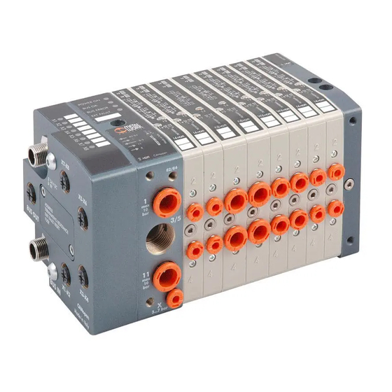
- Page 2 Les électrodistributeurs Heavy-Duty Multimach – AS-Interface sont utilisés Heavy-Duty Multimach – AS-Interface valves are used to connect HDM pour connecter les îlots HDM à un bus AS-I. En conformité avec les islands to an AS-I network. In compliance with V2.1 and V3.0 spécifications AS-Interface V2.1, ils offrentdes fonctions de diagnostiques AS-Interface specifications, they offer diagnostic functions and are et sont disponibles selon le modèle avec une adressage standard ou un...
-
Page 3: Installation
2. INSTALLATION 2. INSTALLATION Il est recommandé d’utiliser les connecteurs femelles MW code It is advisable to use MW code 0226950151 code female connectors to 0226950151 pour connecter les modules d’électrodistributeurs. connect the valve modules. C’est la seule façon d’assurer une protection IP65. This is the only way to ensure IP65 protection. - Page 4 3. ADDRESSAGE 3. ADDRESS 3.1 ASSIGNER L’ADRESSAGE DE L’ESCLAVE AS-I 3.1 ASSIGNING THE AS-I SLAVE ADDRESS Avant de connecter un esclave au système bus, il est recommandé de lui Before connecting a slave to the bus system, it is advisable to assign it a assigner une adresse libre avec l’unité...
- Page 5 3.5 SOLENOID OUTPUT ADDRESSES FOR DOUBLE NODE 3.5 ADRESSAGE DES SORTIES BOBINE POUR NOEUD DOUBLE Example of units with Exemple d’îlot avec 2 Exemple d’îlot avec 8 Example of units with 8 monostable valves* 4 bistable valves* électrodistributeurs bistables* électrodistributeurs monostables* O1 O2 O3 O4 O5 O6 O7 O8 O1 O2 O3 O4 O5 O6 O7 O8 * Mixed combinations are possible.
- Page 6 Type AO- 4 / AP-4 AE- 4 AE - 8 Type AO- 4 / AP-4 AE- 4 AE - 8 Description 4 sorties / 4 entrées 4 sorties / 4 entrées 8 sorties / 8 entrées Description 4 output/4 input 4 output/4 input 8 out/8 input (noeud double)
- Page 7 5. CARACTERISTIQUES DES MODULES AVEC ADRESSAGE ETENDU A/B 5. FEATURES OF THE MODULES WITH EXTENDED A/B ADDRESS 5.1 ASSIGNING THE AS-I SLAVE ADDRESS 5.1 AFFECTATION DE L’ADRESSE DE L’ESCLAVE AS-I The address of the valve modules is only allowed with the address units L’adressage des modules distributeurs est alloué...
-
Page 8: Caracteristiques Techniques
5.4 CARACTERISTIQUES TECHNIQUES 5.4 TECHNICAL DATA Type AS- 3 AZ- 3 AS - 6 AZ - 6 Type AS- 3 AZ- 3 AS - 6 AZ - 6 Description 4 sorties 4 sorties 8 sorties 8 sorties Description 4 output 4 output 8 out 8 out... - Page 9 Type AO- 3 / AP-3 AE- 3 AE - 6 Type AO- 3 / AP-3 AE- 3 AE - 6 Description 4 output/4 input 4 output/4 input 8 out/8 input Description 4 sorties/4 sorties 4 sorties/4 sorties 8 sorties/ 8 entrées (double node) (noeud double) As-i version...
- Page 10 BRANCHEMENT DES CAPTEURS (ENTREES PNP) CONNECTING THE SENSORS (PNP INPUTS) Utiliser des connecteurs M8X1 ou M12X1 suivant le modèle de capteur à Use connectors M8X1 or M12X1 according to the model to connect the raccorder. Bloquer la bague de serrage pour prévenir tout sensors.
- Page 11 NOTES NOTES...
- Page 12 NOTES NOTES www.metalwork.eu ELZZZZ115 FRA_GB - IM01 - 07/2013...


Need help?
Do you have a question about the HDM Series and is the answer not in the manual?
Questions and answers