Table of Contents
Advertisement
Advertisement
Table of Contents

Subscribe to Our Youtube Channel
Related Manuals for NCR RealPOS XR6


Summary of Contents for NCR RealPOS XR6
- Page 1 USER GUIDE NCR RealPOS XR6 (7603) Release 1.0 B005-0000-2400 Issue A...
- Page 2 NCR, therefore, reserves the right to change specifications without prior notice. All features, functions, and operations described herein may not be marketed by NCR in all parts of the world. In some instances, photographs are of equipment prototypes. Therefore, before using this document, consult with your NCR representative or NCR office for information that is applicable and current.
- Page 3 Audience This book is written for hardware installer/service personnel, system integrators, and field engineers. Notice: This document is NCR proprietary information and is not to be disclosed or reproduced without consent. Safety Requirements The NCR RealPOS XR6 conforms to all applicable legal requirements. To view the compliance statements see the NCR RealPOS Terminals Safety and Regulatory Statements (B005-0000-1589).
- Page 4 Use only 3-wire extension cords that have 3-prong grounding plugs and 3-pole receptacles that accept the product’s plug. Repair or replace damaged or worn cords immediately. References • NCR RealPOS XR6 Site Preparation Guide (B005-0000-2401) • NCR RealPOS XR6 Hardware Service Manual (B005-0000-2402) • NCR RealPOS XR6 Parts Identification Manual (B005-0000-2403)
-
Page 5: Table Of Contents
ACPI Processor C-States Operator Displays NCR 5943 12.1-Inch LCD NCR 5943 15-Inch LCD NCR 5967 12-Inch Touch LCD NCR 5967 15-Inch Touch LCD NCR 5954 15-Inch DynaKey NCR 5982 6.5-Inch LCD Display NCR 5976 2x20 LCD Customer Display Keyboards NCR 5932 Keyboards... - Page 6 Keyboard Power NCR 5932-222x 64-Key PS/2 POS Keyboard NCR 5932-5xxx USB Alphanumeric Big Ticket Keyboard Features NCR 5932-65xx PS/2 Programmable POS Keyboard NCR 5932-66xx USB Programmable POS Keyboard Printers NCR 7167 Printer NCR 7168 Printer NCR RealPOS 7197 Printer NCR 7198 Printer...
- Page 7 Chapter 3: Disk Image Backup and Recovery Tool Introduction Running the Recovery Tool Starting the Recovery Tool Main Screen Check and Repair Disk Save or Load Image Change Settings Shutdown or Reboot System Information Save Or Load Image Saving An Image Loading An Image Change Settings Change Network Settings...
- Page 8 viii Restoring Factory Settings BIOS Default Values Main Menu Advanced Menu Chipset Boot Menu Chapter 6: BIOS Updating Procedure Introduction Prerequisites Creating the Bootable Media Creating a Bootable CD Creating a Bootable USB Memory Drive BIOS Updating Procedures Chapter 7: Maintenance Cabinet Cleaning Procedures Touch Screen Cleaning Procedures MSR Cleaning Procedures...
-
Page 9: Chapter 1: Product Overview
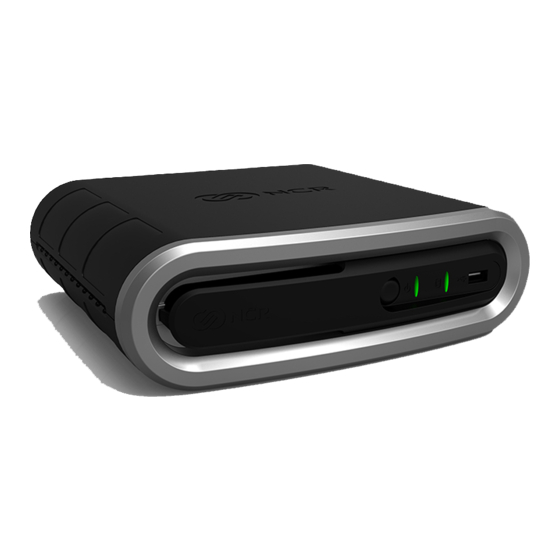
Chapter 1: Introduction The NCR RealPOS XR6 (also known as NCR 7603) is a compact POS solution that combines the reliability and security of a retail-hardened POS terminal with the performance and flexibility of industry-standard PC technology. With an open architecture and Intel®... - Page 10 Product Overview Modular Configuration Stacked Configuration...
- Page 11 Product Overview An optional stand is available to mount the terminal vertically. Vertical Stand Configuration Flush Wall Mount (7409-K502)
-
Page 12: Operator Controls
Product Overview Operator Controls LED Diagnostic Indicators on page 34.Diagnostics on page for more information about the LED Diagnostic Indicators. Cabinet Security The 7603 has easy access to the internal components. However, the case can be secured to a fixed object (desk, pole, etc) by attaching a standard Kensington lock to the Security Hasp. -
Page 13: Serial Number/Model Number Label
Product Overview Serial Number/Model Number Label The serial number and model number are included on the Certification Label located on bottom of the terminal. A Microsoft Certificate of Authenticity (COA) label is included if the terminal is ordered and shipped with a pre-installed Microsoft Operating System. There are two types of Microsoft COA stickers. -
Page 14: Features
Product Overview Features Motherboard • Intel's Haswell Chipset • Up to 8GB DDR3 Memory, 1333 MHz, 2 Memory Sockets • Serial ATA (SATA) Hard Drive Interface • High-speed Gigabit Ethernet • Four Powered Serial ports • HDMI Connector • Display Port Connector •... -
Page 15: Graphics
Product Overview • Windows Embedded POSReady 2009 • SUSE Linux SLEPOS11 SP2 Graphics The Motherboard has integrated graphics on board. PCI Express x16 graphics adapters. are not supported. Output ports Dual independent displays in Concurrent (Clone) and Extended Desktop modes are supported by the 7603. -
Page 16: Power Management
Product Overview Power Management The BIOS supports the Advanced Configuration and Power Management Interface (ACPI) 3.0 specification. A key feature of ACPI is that the operating system, not the BIOS, configures and implements power management. The 7603 terminal supports the Global system power states defined by ACPI: G3 Mechanical Off A computer state that is entered and left by a mechanical means. -
Page 17: Acpi Sleep States (S0 - S5)
S1 sleeping state except that the CPU and system cache context is lost (the OS is responsible for maintaining the caches and CPU context). Control starts from the processor's reset vector after the wake event. In NCR systems, during S3, power is only provided to the on-board USB ports. - Page 18 1-10 Product Overview Power State **S3 Suspend S0Working S1Standby S4Hibernate **S5Soft Off to RAM Supported Description Fully • Video Back • Video Back • Video Back Functional Light Off Light Off Light Off • HDD Off • HDD Off • HDD Off •...
-
Page 19: Enabling Wake On Lan
Product Overview 1-11 Enabling Wake on LAN In order for Wake on LAN to function the Network driver must be enabled (factory default). The procedure for enabling the driver depends on which operating system you are using. Windows 7 Computer >>... - Page 20 1-12 Product Overview 2. Select Network adapters. 3. Right-click Intel(R) Ethernet Connection J217-LM >> Properties. 4. Under the Power Management tab, Wake on Magic Packet and Wake on Pattern Match and Wake on Magic Packet from power off state option boxes should be checked. Select after making any changes.
-
Page 21: Acpi Processor C-States
Product Overview 1-13 ACPI Processor C-States ACPI defines the power state of system processors while in the G0 working state as being either active (executing) or sleeping (not executing). Processor power states are designated C0, C1, C2, C3, …Cn. The C0 power state is an active power state where the CPU executes instructions. The C1 through Cn power states are processor sleeping states where the processor consumes less power and dissipates less heat than leaving the processor in the C0 state. -
Page 22: Operator Displays
Operator Displays NCR 5943 12.1-Inch LCD The NCR 5943 LCD is an LED backlit LCD display (XGA, 1024 x 768). The display is powered by the terminal from a +12V USB Plus Power port. The remote mount must be ordered separately. -
Page 23: Ncr 5943 15-Inch Lcd
1-15 NCR 5943 15-Inch LCD The NCR 5943 LCD is an LED backlit LCD display (XGA, 1024 x 768). The display is powered by the terminal from a +12V USB Plus Power port. The remote mount must be ordered separately. -
Page 24: Ncr 5967 12-Inch Touch Lcd
Product Overview NCR 5967 12-Inch Touch LCD The NCR 5967 Touch LCD is an LED backlit LCD display (XGA, 1024 x 768) with capacitive touch screen. The display is powered by the terminal from a +12V USB Plus Power port. The remote mount must be ordered separately. -
Page 25: Ncr 5967 15-Inch Touch Lcd
1-17 NCR 5967 15-Inch Touch LCD The NCR 5967 Touch LCD is an LED backlit LCD display (XGA, 1024 x 768) with capacitive touch screen. The display is powered by the terminal from a +12V USB Plus Power port. The remote mount must be ordered separately. -
Page 26: Ncr 5954 15-Inch Dynakey
Product Overview NCR 5954 15-Inch DynaKey The NCR RealPOS 5954 USB DynaKey is a Point-of-Sale (POS) keypad with a built-in 15- inch flat panel Liquid Crystal Display (LCD). Unique to the DynaKey is a set of ATM- style keys (DynaKeys), which are located beside the display. The functions of these keys change depending on the software application appearing on the LCD. -
Page 27: Ncr 5982 6.5-Inch Lcd Display
Product Overview 1-19 NCR 5982 6.5-Inch LCD Display The 5982 LCD Display is a terminal-powered color 6.5 Inch VGA LCD. Features • 5-inch VGA Monochrome LCD (640 x 480 VGA) • Contrast Control • LED Back Light • Keyboard Mount •... -
Page 28: Ncr 5976 2X20 Lcd Customer Display
Product Overview NCR 5976 2x20 LCD Customer Display The NCR RealPOS 5976-1xxx Customer Display is a 2-line x 20-character LED backlit Liquid Crystal Display (LCD), which can display any downloadable codepage of single byte characters. It supports both RS-232 and USB interfaces. - Page 29 • Table Mount, 4-in. Post • Table Mount, 8-in. Post • Table Mount, 12-in. Post • Table Mount, 16-in. Post • Integrated Mount for NCR 7456, 7457, 7458 Character Sets • Support for 19 character sets • 3 Character sets in base unit •...
-
Page 30: Keyboards
• NCR 5932-66xx USB Compact Keyboard Keyboard Power The RealPOS XR6 supplies power to the PS/2 keyboard even when in the OFF state. This is for configurations that require the terminal to turn on when a key is pressed. Most NCR PS/2 keyboards have a Power ON LED which stays illuminated, indicating power is present in the keyboard. -
Page 31: Ncr 5932-222X 64-Key Ps/2 Pos Keyboard
Product Overview 1-23 NCR 5932-222x 64-Key PS/2 POS Keyboard The NCR 64-Key POS Keyboard, designed for checkout environments where alpha entry is not required, includes 55 assignable function keys and a numeric keypad with 11 keys. Keylock Status Indicator 19746 Features •... - Page 32 1-24 Product Overview Keylock The Big Ticket and 64-key keyboards have a four-position keylock switch. The table following explains the keylock positions. Abbreviation Position Description Exception Used by the customer or service representative to perform low-level programming such as terminal diagnostics, configuring the terminal, or loading the terminal.
- Page 33 Product Overview 1-25 MSR (Magnetic Stripe Reader) The MSR is an optional feature that provides support for reading magnetically coded data cards. The keyboards support two different types of MSR: • ISO Tracks 1, 2, and 3 • JIS-II and ISO Track 2 (Big Ticket and full-featured 64-key keyboards only) Note: MSR signals are routed to the Wedge controller and passed into the system keyboard data stream.
-
Page 34: Ncr 5932-5Xxx Usb Alphanumeric Big Ticket Keyboard
Product Overview NCR 5932-5xxx USB Alphanumeric Big Ticket Keyboard Keylock 19586 The NCR USB Alphanumeric Big Ticket Keyboard is a multifunction keyboard that is two keyboards built into one. The keyboard consists of two major sections: • 38-key POS keyboard •... -
Page 35: Ncr 5932-65Xx Ps/2 Programmable Pos Keyboard
Product Overview 1-27 NCR 5932-65xx PS/2 Programmable POS Keyboard The NCR 5932 PS/2 Programmable POS Keyboard is a multifunctional keyboard that is two keyboards built into one. The keyboard consists of two major sections: • 32-key Point-Of-Sale Keyboard • PC type Alphanumeric Keyboard... -
Page 36: Ncr 5932-66Xx Usb Programmable Pos Keyboard
1-28 Product Overview NCR 5932-66xx USB Programmable POS Keyboard The NCR 5932 PS/2 Programmable POS Keyboard is a multifunctional keyboard that is two keyboards built into one. The keyboard consists of two major sections: • 32-key Point-Of-Sale Keyboard • PC type Alphanumeric Keyboard The keyboard includes the following features: •... -
Page 37: Printers
Printers NCR 7167 Printer The NCR 7167 Printer is a fast, quiet, relatively small and very reliable multi function printer. It prints receipts, validates and prints checks, and prints on a variety of single or multiple part forms. There is not journal as it is kept electronically by the host terminal. -
Page 38: Ncr 7168 Printer
Product Overview NCR 7168 Printer The NCR 7168 Printer is a fast, quiet, relatively small and very reliable multiple-function printer with front and back printing on the receipt paper capability. It prints receipts, validates and prints checks, and prints on a variety of single- or multiple-part forms. -
Page 39: Ncr Realpos 7197 Printer
1-31 NCR RealPOS 7197 Printer The NCR 7197 Printer is a fast, quiet, relatively small and very reliable printer. The printer can connect through a USB port or a serial port. It receives power from the 24V connector on the terminal or from an external power supply. -
Page 40: Ncr 7198 Printer
Product Overview NCR 7198 Printer The NCR 7198 printer is a fast, quiet, relatively small and very reliable printer with front and back printing on the receipt paper capability. The printer can connect through a USB port or a serial port. It can receive power from a power supply or through a USB+ power cable. -
Page 41: Chapter 2: Hardware Installation
• Install the RealPOS XR6 near an electrical outlet that is easily accessible. Use the power cord as a power disconnect device. • Do not permit any object to rest on the power cord. Do not locate the RealPOS XR6 where the power cord can be walked on. -
Page 42: Chapter 2: Diagnostics
2-34 Hardware Installation Diagnostics Chapter 2: LED Diagnostic Indicators The two front panel LEDs also function as diagnostic indicators, defined as follows. Note: The cell colors indicate the color of the LED at that particular time. Current Disk Suspect System System Power LED Activity... - Page 43 Hardware Installation 2-35 Current Disk Suspect System System Power LED Activity Corrective Action Component State Operation • OFF Power System • OFF 1. Check AC power to • AC Present • Not in Standby 2. Check P/S • External 3. Check connection P/S ON between unit and 4.
- Page 44 2-36 Hardware Installation Current Disk Suspect System System Power LED Activity Corrective Action Component State Operation POST Memory Memory Flashing 1. Check for properly Issue (1/Sec) installed memory 2. Replace memory 3. Replace Motherboard POST Motherboard No Display Flashing Replace Motherboard 1/4 Sec) POST Display...
- Page 45 Hardware Installation 2-37 Current Disk Suspect System System Power LED Activity Corrective Action Component State Operation Boot Time Boot Media (HDD, HDD is Boot Device: LAN) 1. Check HDD status in BIOS Setup 2. Check connections between HDD and Motherboard 3.
-
Page 46: Installing The Terminal
2-38 Hardware Installation Installing the Terminal 1. Connecting the External Cables 2. Connect the external cables to the connectors located on the rear of the unit. There is also a USB connector on the Front Panel. See the following sections for each component. -
Page 47: Installing The Keyboard And Mouse
Hardware Installation 2-39 Installing the Keyboard and Mouse The 7603 supports USB and PS/2 type keyboards. Only USB mice are supported. See the following examples of supported configurations. USB Keyboard and USB Mouse PS/2 Keyboard and USB Mouse Note: PS/2 Extension Cables cannot be used on PS/2 Keyboards with a Glide Pad. - Page 48 2-40 Hardware Installation USB Keyboard w/Glide Pad...
-
Page 49: Connecting Ac Power
The 7603 power supply is an external 24 V power brick. Caution: The 7603 requires the NCR 24 V power supply that is shipped with the terminal. Use of other power bricks may cause damage to the unit. 1. Connect the Power Supply cable to the DC Power connector on the terminal. -
Page 50: Disconnecting The Power Cable
2-42 Hardware Installation Disconnecting the Power Cable The Power Cable connector locks into position when connected to the terminal and cannot be removed by simply pulling on the cable. You must grasp the connector and slide the outside housing out from the terminal to unlock it from the terminal connector. -
Page 51: Ps/2 Cable Connection
Hardware Installation 2-43 PS/2 Cable Connection The PS/2 Cable should be secured with a Tie Wrap. On units configured with an Extended I/O Daughter Card the Tie Wrap Holder is used to secure the Cable. If the Daughter Card is not present the cable is secured to the hook located on the Rear Panel Knockout. -
Page 52: Installing A Transaction Printer
2-44 Hardware Installation Installing a Transaction Printer The printers can connect through a USB connector or an RS-232 connector. USB Installation Connect the Powered USB Printer Interface Cable to the USB Connector and Power Connector on the printer and to the 24 V Powered USB Connector on the terminal. -
Page 53: Rs-232 Installation
Hardware Installation 2-45 RS-232 Installation 1. Connect the RS-232 Printer Interface Cable to the RS-232 connector on the printer and to a non-poweredRS-232 connector on the terminal. Note: The factory default setting for the RS-232 ports is powered. See the Appendix: Powered Serial Port Settings. -
Page 54: Installing A Remote Display
2-46 Hardware Installation Installing a Remote Display The Standard Remote Mount (5964-K031) is used to mount the following NCR displays. • NCR RealPOS 5943 12.1-Inch Monitor • NCR RealPOS 5943 15-Inch Monitor • NCR RealPOS 5967 12.1-Inch Touch Monitor • NCR RealPOS 5967 15-Inch Touch Monitor 21151b 1. - Page 55 Hardware Installation 2-47 2. Route the cable(s) down through the mount and out the back of the base. 26474 3. Connect the cable to the proper connector on the host terminal. See the following sections for cable connections to the host terminal.
-
Page 56: Ncr 5943/5967 12-Inch Lcd Cable Connections
2-48 Hardware Installation NCR 5943/5967 12-inch LCD Cable Connections The following illustrations show the cable connections for the 5943 LCD and the 7603 terminal. There are two cables required. • VGA or DVI cable for video • Powered Universal Serial Bus (USB) for data and power VGA/DVI Connections Connect either a VGA or a HDMI to DVI cable. - Page 57 Connect the Powered USB Cable to the 5943 LCD and to one of the 12V Powered USB connectors on the 7603 terminal. For more information see: • the NCR RealPOS 5943 12" LCD User Guide (B005-0000-2043) • the NCR RealPOS 5967 12" LCD User Guide (B005-0000-2182)
-
Page 58: Ncr 5943/5967 15-Inch Lcd Cable Connections
2-50 Hardware Installation NCR 5943/5967 15-inch LCD Cable Connections The following illustrations show the cable connections for the 5943 LCD and the 7603 terminal. There are two cables required. • VGA or DVI cable for video • Powered Universal Serial Bus (USB) for data and power VGA/DVI Connections Connect either a VGA or an HDMI to DVI cable. - Page 59 Connect the Powered USB Cable to the 5943 LCD and to one of the 12V Powered USB connectors on the 7603 terminal. For more information see: • the NCR RealPOS 5943 15" LCD User Guide (B005-0000-2182) • the NCR RealPOS 5967 15" LCD User Guide (B005-0000-2193)
-
Page 60: Ncr 5954 Usb Dynakey Cable Connections
2-52 Hardware Installation NCR 5954 USB DynaKey Cable Connections The DynaKey connects to the terminal via two cables. • DVI or VGA cable for video • Powered Universal Serial Bus (USB) for data and power VGA/DVI Cable Connections Connect the cable to the DVI connectors on the DynaKey and terminal. - Page 61 Hardware Installation 2-53 Powered USB Cable Connections Connect the Powered USB Cable to the DynaKey and to one of the Powered USB connectors on the terminal.
-
Page 62: Installing An Ncr 5982 6.5-Inch Lcd
2-54 Hardware Installation Installing an NCR 5982 6.5-Inch LCD 1. Remove the Base from the Display (2 screws). Screws 23162... - Page 63 Hardware Installation 2-55 2. Route the VGA and Power cables up through the bottom of the Base and connect them to the Display. Note: The power cable can be either an External Power Supply or a Powered USB cable. Power 23435 ‘...
- Page 64 2-56 Hardware Installation 5. Connect the Power Cable: External Power Supply a. Connect the VGA cable to the VGA port on the host terminal. b. Connect the AC Cord to the Power Supply and to an AC source.
- Page 65 Hardware Installation 2-57 Terminal Powered (7446-30303131) a. Connect the VGA cable to the VGA port on the host terminal. b. Connect the Power Cable to the Powered 12V USB port on the host terminal.
-
Page 66: Installing A 5975/5976 Customer Display
Hardware Installation Installing a 5975/5976 Customer Display The terminal supports two customer displays. • NCR 5975 Graphical Customer Display (VFD) • NCR 5976 Remote Customer Display (LCD) There are four different length posts available, in four inch increments. 515.6 mm 20.30 in... - Page 67 Hardware Installation 2-59 1. Locate the Display Mount within 4 meters (13 ft.) of the host terminal. 2. Determine if the cable should be routed down through the mounting surface or if it should be run on top of the surface. Drill a hole if necessary. 3.
-
Page 68: Rs-232 Interface
2-60 Hardware Installation 5. Route the Interface Cable through the Post and assemble the Post components. Raised extension faces the front of the display Display Swivel 29354 6. Connect the Display Cable to the terminal. RS-232 Interface Connect the I/F cable to a powered RS-232 connector on the terminal. Note: The factory default settings for the COM1 and COM2 ports are powered by default. -
Page 69: Usb Interface
Hardware Installation 2-61 USB Interface Connect the I/F cable to the powered 12V Powered USB connector on the terminal. -
Page 70: Installing A Secondary Display (Dual Display)
2-62 Hardware Installation Installing a Secondary Display (Dual Display) The 7603 Motherboard features a 15 pin D-Shell VGA connector, an HDMI connector, and a DisplayPort connector. Dual independent displays are supported for any combination of these outputs, with display resolutions up to 1920x1200 on each. Dual display mode can be a clone (same video data displayed on both displays) or an extended desktop (the desktop spans across both displays). -
Page 71: Setting The Display Mode
Hardware Installation 2-63 Setting the Display Mode Note: Use this procedure for configuring displays that are connected to the Motherboard ports. The dual mode is configured with the Intel® Graphics and Media Control Panel. Right- click the Desktop. From the menu select Graphics Properties to display the panel. - Page 72 2-64 Hardware Installation 3. Select the display Display Mode. Configuration Description Mode Single Display Single display (even if two displays are connected) Clone Displays Drives both displays with the same video content. Extended Drives the both displays with the desktop that spans from one Desktop display onto the other.
- Page 73 Hardware Installation 2-65 Applications may behave differently in a multi-monitor configuration depending on their implementation: • Standard Windows applications that use the GDI (Graphics Device Interface) will clip the window to each display and accelerate the images separately using the display hardware.
-
Page 74: Installing A Cash Drawer
Hardware Installation Installing a Cash Drawer The small footprint of the RealPOS XR6 permits the terminal to rest directly on most cash drawers. However, other peripherals like the keyboard or printer may or may not fit. The Cash Drawer can connect to the Cash Drawer connector or to the transaction printer. -
Page 75: Installing Two Cash Drawers
Hardware Installation 2-67 Installing Two Cash Drawers The 7603 supports a 2-drawer configuration with a Y-cable (1416 C372 0006). -
Page 76: Replacing The Hard Disk Drive
2-68 Hardware Installation Replacing the Hard Disk Drive The Hard Disk Drive (HDD) is mounted on the inside of the Top Cover. 1. Slide the Cover Latch on the bottom of the unit forward to unlock the Top Cover. Note: First remove the Security Lock on the rear if present. - Page 77 Hardware Installation 2-69 3. Disconnect the SATA cable(s) from the storage device(s). 4. Loosen the thumbscrews (2) that secure the HDD Assembly to the Top Cover. 5. Remove the HDD Assembly.
- Page 78 2-70...
-
Page 79: Chapter 3: Disk Image Backup And Recovery Tool
Disk Image Backup and Recovery Tool Chapter 3: Introduction This chapter discusses procedures on how to backup or recover the POS image. The terminal has a recovery tool that performs a complete backup of the whole HDD/SSD. This includes the operating system, all files, data and the database itself if it is installed on the HDD/SSD, making an exact duplicate of everything contained on the terminal. -
Page 80: Running The Recovery Tool
3-72 Disk Image Backup and Recovery Tool Running the Recovery Tool Starting the Recovery Tool The Recovery Tool Button is located on the I/O Panel. 1. Begin with terminal OFF. 2. Using a pen, stylus, (or similar object) press (and hold) the recessed Recovery Tool Button. -
Page 81: Main Screen
Disk Image Backup and Recovery Tool 3-73 Main Screen When the terminal boots the Main Screen is displayed. Check and Repair Disk This button runs Checkdisk, which checks the consistency of the HDD/SSD and the Windows file system. Failures can occurs in the Windows file system and prevent Windows from starting. -
Page 82: Save Or Load Image
3-74 Disk Image Backup and Recovery Tool Save Or Load Image This function is used to either Save or Load an image from a device. 1. On the Main Screen, click on Save or Load Image. 2. Enter the Password. The factory default password is Recovery1234. -
Page 83: Saving An Image
Disk Image Backup and Recovery Tool 3-75 Saving An Image The Select Image Location screen displays a terminal with three sets of In/Out arrow buttons, indicating the direction of data flow when selected. Arrows pointing away from the terminal are used to Save images to a device. Arrows pointing towards the terminal are used to Load an image. - Page 84 3-76 Disk Image Backup and Recovery Tool Backups to separate slots in the Recovery Tool only increase the total storage required by the amount of data added to the image. When the contents of the OS partition become too large to store in the 8GB local Recovery Partition then one of the alternate storage methods available (USB or network) should be used to store backups.
- Page 85 Disk Image Backup and Recovery Tool 3-77 2. Click on the Button. If this is the first backup performed on this POS then the image is automatically saved as a Site backup.
-
Page 86: Loading An Image
3-78 Disk Image Backup and Recovery Tool If a backup already exists then you have the choice of performing either a Site or User backup. • Site Image - Use this option immediately after all application components have been loaded and setup for initial operation, or for base image updates. •... - Page 87 Disk Image Backup and Recovery Tool 3-79 1. Click on the arrow that points from the desired load device to the terminal. Example: Click on the USBLoad Button. 2. Click on the Button.
- Page 88 3. Select the Image Type. • User Image - Most recent routine backup. • Site Image - Image of the terminal after application components were loaded. • Factory Image - This is the NCR Base Image as shipped from the factory.
- Page 89 Disk Image Backup and Recovery Tool 3-81 4. Click to to apply the image. Caution: All the information in the current productive/working image on the drive is lost with this operation! A progress bar is displayed as the image is applied.
- Page 90 3-82 Disk Image Backup and Recovery Tool A message is displayed when the load is complete. Reboot the POS.
-
Page 91: Change Settings
Disk Image Backup and Recovery Tool 3-83 Change Settings On the Main Screen, click on Change Settings. There are four functions available on the Change Settings screen. • Change Network Settings • Change Password • Replace Recovery Image • Change Language... -
Page 92: Change Network Settings
3-84 Disk Image Backup and Recovery Tool Change Network Settings 1. On the Change Settings Screen, click on Change Network Settings. 2. Enter the Password. -
Page 93: Change Password
Disk Image Backup and Recovery Tool 3-85 3. Enter the network configuration settings and then click [Enter]. Change Password 1. On the Change Settings Screen, click on Change Password 2. Enter the new Password. Click [Enter]. -
Page 94: Replace Recovery Image
3-86 Disk Image Backup and Recovery Tool If you have forgotten/lost the password you can click on Lost Password. A unique code is generated that you can provide to NCR Support to get a new temporary password. Replace Recovery Image This feature is used to update the Recovery Tool and the environment that it runs in. -
Page 95: Change Language
Disk Image Backup and Recovery Tool 3-87 2. Click on the source of the Recovery Image. 3. Complete the image replacement in the same manner as with the POS Site/User image restore procedures. Change Language 1. On the Change Settings Screen, click on Change Language... -
Page 96: Creating A Disk Image
This terminal has a Recovery Button that permits end users to quickly restore a disk back up from a hidden partition on the NCR system storage. To utilize this valuable feature the image must be created using NCR tools. Tools are available from NCR at: http://www5.ncr.com/support/support_drivers_patches_radiant.asp?Class=Hospitality/... -
Page 97: Chapter 4: Bios Setup
1. Connect an alphanumeric USB keyboard to the terminal. 2. Apply power to the terminal. 3. When you see the NCR logo displayed press [Del]. How to Select Menu Options The following keyboard controls are used to select the various menu options and to make changes to their values. -
Page 98: Bios Default Values
4-90 BIOS Setup BIOS Default Values NCR BIOS Version: 8.5.6.0 Main Menu System Language [English] System Time (variable) System Date (variable) Advanced Menu Network PCE Loading [Disabled] Mass Stprage [topm ROM Loading [Enabled] ► ACPI Settings Enable ACPI Auto Configuration... - Page 99 BIOS Setup 4-91 ► CPU Configuration Active Processor Cores [All] Limit CPUID Maximum [Disabled] Execute Disable Bit [Enabled] Intel Virtualization Technology [Enabled] Hardware Prefetcher [Enabled] Adjacent Cache Line Prefetch [Enabled] CPU AES [Enabled] EIST [Enabled] Intel TXT(LT) Support [Disabled] ► SATA Configuration SATA Controller(s) [Enabled] SATA Mode Selection...
- Page 100 4-92 BIOS Setup . ►Serial ATA Port 0/1/2 . Port 0/1/2 [Enabled] . Hot Plug [Enabled] . Mechanical Presence Switch [Disabled] . External SATA [Disabled] . SATA Device Type [Hard Disk Drive] . Spin Up Device [Disabled] ► AMT Configuration Intel AMT [Disabled] BIOS Hotkey Pressed...
- Page 101 BIOS Setup 4-93 SMART Status ► USB Configuration Legacy USB Support [Enabled] XHCI Hand-off [Enabled] EHCI Hand-off [Disabled] Port 60/64 Emulation [Enabled] USB hardware delays and time-outs: USB transfer time-out [20 sec] Device reset time-out [20 sec] Device power-up delay [Auto] ►...
- Page 102 4-94 BIOS Setup . IRQ [IRQ11] . Device Mode [Standard Serial Po. . .] . ►Serial Port 4/D Configuration . Serial Port [Enabled] . Device Settings IO=2E8h; IRQ=10; . I/O Base Address [0x2E8] . IRQ [IRQ10] . Device Mode [Standard Serial Po. . .] .
- Page 103 BIOS Setup 4-95 ► Serial Port Console Redirection COM0 (Disabled) Console Redirection Port is Disabled COM1(Pci Bus0,Dev0,Func0) (Disabled) Console Redirection Port is Disabled Serial Port for Out-of-Band Management/Windows Emergency Management Ser- vices (EMS) Console Redirection [Disabled] . ►Console Redirection Settings .
-
Page 104: Chipset
4-96 BIOS Setup Chipset ► PCH-IO Configuration . ► PCI Express Configuration . PCI Express Clock Gating [Enabled] . DMI Link ASPM Control [Enabled] . DMI Link Extended Synch Control [Disabled] . PCIE Root Port Function Swapping [Enabled] . Subtractive Decode [Disabled] . - Page 105 BIOS Setup 4-97 . ► USB Configuration . EHCI [Enabled] . USB Ports Per-Port Disable Control [Disabled] . ► PCH Azalia Configuration . Azalia [Auto] . Azalia Docking Support [Disabled] . Azalia PME [Disabled] . ► BIOS Security Configuration . SMI Lock [Disabled] .
- Page 106 4-98 BIOS Setup . ALS Support [Enabled] . DVMT Total Gfx Mem [128MB] . Gfx Low Power Mode [Enabled] . Panel Power Enable [Disabled] . ►LCD Control . . Primary IGFX Boot Display [VBIOS Default] . . LCD Panel Type [VBIOS Default] .
-
Page 107: Boot Menu
BIOS Setup 4-99 Boot Menu Boot Configuration Setup Prompt Timeout Bootup NumLock State [On] Quiet Boot [Disabled] Fast Boot [Disabled] Boot mode select [Legacy] Fixed Boot Order Priorities Boot Option #1 [Network] Boot Option #2 [Hard Disk: ST250VT . . . ] Boot Option #3 [USB Key] Boot Option #4... - Page 108 4-100...
-
Page 109: Chapter 5: Initial Terminal Imaging
3. Power on the terminal and boot from the USB Flash Drive. This can be done by pressing during the boot and choosing the USB option (NCR), or by entering BIOS Setup and changing the boot order. 4. The system boots in the Windows PE OS environment. Press on the keyboard at the confirmation prompt to re-image the terminal. -
Page 110: Chapter 5: Bios Setup
1. Connect an alphanumeric USB keyboard to the terminal. 2. Apply power to the terminal. 3. When you see the NCR logo displayed press [Del]. How to Select Menu Options The following keyboard controls are used to select the various menu options and to make changes to their values. -
Page 111: Bios Default Values
Initial Terminal Imaging 5-103 BIOS Default Values NCR BIOS Version: 8.5.6.0 Main Menu System Language [English] System Time (variable) System Date (variable) Advanced Menu Network PCE Loading [Disabled] Mass Stprage [topm ROM Loading [Enabled] ► ACPI Settings Enable ACPI Auto Configuration... - Page 112 5-104 Initial Terminal Imaging ► CPU Configuration Active Processor Cores [All] Limit CPUID Maximum [Disabled] Execute Disable Bit [Enabled] Intel Virtualization Technology [Enabled] Hardware Prefetcher [Enabled] Adjacent Cache Line Prefetch [Enabled] CPU AES [Enabled] EIST [Enabled] Intel TXT(LT) Support [Disabled] ►...
- Page 113 Initial Terminal Imaging 5-105 . ►Serial ATA Port 0/1/2 . Port 0/1/2 [Enabled] . Hot Plug [Enabled] . Mechanical Presence Switch [Disabled] . External SATA [Disabled] . SATA Device Type [Hard Disk Drive] . Spin Up Device [Disabled] ► AMT Configuration Intel AMT [Disabled] BIOS Hotkey Pressed...
- Page 114 5-106 Initial Terminal Imaging SMART Status ► USB Configuration Legacy USB Support [Enabled] XHCI Hand-off [Enabled] EHCI Hand-off [Disabled] Port 60/64 Emulation [Enabled] USB hardware delays and time-outs: USB transfer time-out [20 sec] Device reset time-out [20 sec] Device power-up delay [Auto] ►...
- Page 115 Initial Terminal Imaging 5-107 . IRQ [IRQ11] . Device Mode [Standard Serial Po. . .] . ►Serial Port 4/D Configuration . Serial Port [Enabled] . Device Settings IO=2E8h; IRQ=10; . I/O Base Address [0x2E8] . IRQ [IRQ10] . Device Mode [Standard Serial Po.
- Page 116 5-108 Initial Terminal Imaging ► Serial Port Console Redirection COM0 (Disabled) Console Redirection Port is Disabled COM1(Pci Bus0,Dev0,Func0) (Disabled) Console Redirection Port is Disabled Serial Port for Out-of-Band Management/Windows Emergency Management Ser- vices (EMS) Console Redirection [Disabled] . ►Console Redirection Settings .
-
Page 117: Chipset
Initial Terminal Imaging 5-109 Chipset ► PCH-IO Configuration . ► PCI Express Configuration . PCI Express Clock Gating [Enabled] . DMI Link ASPM Control [Enabled] . DMI Link Extended Synch Control [Disabled] . PCIE Root Port Function Swapping [Enabled] . Subtractive Decode [Disabled] . - Page 118 5-110 Initial Terminal Imaging . ► USB Configuration . EHCI [Enabled] . USB Ports Per-Port Disable Control [Disabled] . ► PCH Azalia Configuration . Azalia [Auto] . Azalia Docking Support [Disabled] . Azalia PME [Disabled] . ► BIOS Security Configuration .
- Page 119 Initial Terminal Imaging 5-111 . ALS Support [Enabled] . DVMT Total Gfx Mem [128MB] . Gfx Low Power Mode [Enabled] . Panel Power Enable [Disabled] . ►LCD Control . . Primary IGFX Boot Display [VBIOS Default] . . LCD Panel Type [VBIOS Default] .
-
Page 120: Boot Menu
5-112 Initial Terminal Imaging Boot Menu Boot Configuration Setup Prompt Timeout Bootup NumLock State [On] Quiet Boot [Disabled] Fast Boot [Disabled] Boot mode select [Legacy] Fixed Boot Order Priorities Boot Option #1 [Network] Boot Option #2 [Hard Disk: ST250VT . . . ] Boot Option #3 [USB Key] Boot Option #4... -
Page 121: Chapter 6: Bios Updating Procedure
The BIOS update can be performed using the following methods: • Bootable USB CD Drive • Bootable USB Memory Device • Network - Refer to the NCR Retail Systems Manager (RSM) Software User's Guide, (B005-0000-1518) for information about this procedure. Prerequisites The following are required to perform a SPI/BIOS update. -
Page 122: Creating The Bootable Media
6-114 BIOS Updating Procedure Creating the Bootable Media Creating a Bootable CD The downloaded file is a CD image file (ISO) containing the files necessary to create a bootable CD. A system with a CD/DVD burner is required to perform this function. 1. -
Page 123: Bios Updating Procedures
1. Insert the media containing the BIOS update software into the terminal. 2. Connect a USB keyboard. 3. Press [F8] during boot (when you see the NCR logo) to enter the Boot Select menu. 4. Select USB:[name of device]. 5. The terminal boots and displays the BIOS Update main menu. - Page 124 6-116 BIOS Updating Procedure Option 2 - Update of BIOS - Always enter Serial/Model/Class This option prompts for Class/Model/Serial information at the beginning of the program and then updates the BIOS only. 1. Highlight Option 2 and press [ENTER]. 2. At the prompt press [ENTER] to enter the Class/Model/Serial Number information (DMI).
-
Page 125: Chapter 7: Maintenance
3. Make sure the glass and screen edges dry completely before using the unit. 4. Do not use sharp objects to clean around the edges of the touch screen MSR Cleaning Procedures MSR Cleaning Cards and MSR Treatment Cards may be purchased from NCR or KIC http://www.ncr-direct.com http://www.kicproducts.com Products. -
Page 126: Msr Treatment Card
7-118 Maintenance MSR Treatment Card The MSR Treatment Card is used to assist in protecting Magnetic Stripe Readers from Electrostatic Discharge (ESD), which can cause failures when swiping cards that have metallic hologram stripes. Swipe the card through the MSR in a smooth motion. Only swipe it down ONCE and up ONCE. -
Page 127: Appendix A: Powered Serial Port Settings
Powered Serial Port Settings Appendix A: The serial ports on the 7603 can be configured as powered or not. The default setting for all the ports is 12 V powered. To change the settings open the Top cover and change the jumpers on the Motherboard using the illustrations below.
Need help?
Do you have a question about the RealPOS XR6 and is the answer not in the manual?
Questions and answers