Table of Contents
Advertisement
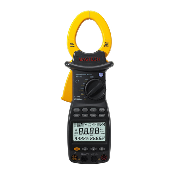
DIGITAL CLAMP METER
OPERATION MANUAL
POWER CLAMP METER
MS2205
OFF
kW
1 PHASE
Ø
1 PHASE
kW/Ø
3 PHASE
A~
HARM
Yrue RMS
V~
Harmonic
HARM
AUTO RANGE
MODE
I
U
SET
Watt
RS232
APS
RST
RS232
LAG
FS
HOLD
LEAD
REC
CAL
COSΦ
SINΦ
MAX
MIN
VA
kWh
PEAK
V1
EN61010-1
COM/V2
600V CAT III
~
MS2205
HOLD
READ
CLEAR
USED
READ
MEMO
°
HzA
PEAK
kWVAh
%THD
kVA
Hz
V3
~
Advertisement
Table of Contents

Related Manuals for Mastech MS2205


Summary of Contents for Mastech MS2205
- Page 1 MS2205 DIGITAL CLAMP METER OPERATION MANUAL HOLD POWER CLAMP METER MS2205 1 PHASE Ø 1 PHASE kW/Ø 3 PHASE HARM Yrue RMS Harmonic HARM AUTO RANGE MODE READ Watt RS232 CLEAR RS232 USED READ HOLD LEAD MEMO ° PEAK COSΦ...
-
Page 2: Table Of Contents
CONTENTS CONTENTS Safety Requirements....1 iagram of Safe Holding ......24 afety Instructions ......2 Power curve diagram......25 afety Sign ........2 Battery-low Indication......26 General Description .....2 Battery Replacement .......26 Features........3 General specification ......28 Appearance ........4 echnical specification ......28 Knob Switch Operations ....6 Accessories ...........29 utton Switch Operations ....7... -
Page 3: Safety Requirements
Safety Requirements Safety Instructions Please carefully read the instruction manual before The three-phase clamp-type digital power meter is using the tester, and pay special attention to “Warning” designed and manufactured in accordance with content. Please follow instructions under “Warning”. international standard, IEC61010-1, and international 1. -
Page 4: Features
2. True effective value measurement: accurate measurement is possible even with serious distortion in current waveform. HOLD POWER CLAMP METER 3. Low-consumption high-speed single-chip MS2205 1 PHASE microprocessor is employed and sophisticated Ø 1 PHASE kW/Ø algorithm is applied, as a result, results can be... -
Page 5: Knob Switch Operations
1. Current clamp size: Φ 50 mm PC, as well as for recording data and data trend curve 2. HOLD button :DATA HOLD button; press down in PC. HOLD button, and the last reading will be held and Knob Switch Operations displayed on the display, and “HOLD”... -
Page 6: Button Switch Operations
Button Switch Operations Under KW-test mode, you can press MODE button to switch the display of active power and passive power; Button descriptions under A/V~ test mode, you can switch the display among Function-selection button total harmonic distortion rate F, r, and harmonic MODE :Test-mode switching button percentage. -
Page 7: Lcd Display
Before pressing RS232 button for data transferring, When reading the saved data, you can press button to search in the forward direction the stored data and the supplied RS232C interface wire shall be connected to RS232C interface socket of the meter show it on LCD. -
Page 8: Instruction Manual
LCD symbol Description LCD symbol Description LCD symbol Description LCD symbol Description Data Data transfer %THD Total harmonics distortion ratio RS232 recording Total harmonics distortion ratio F H01F Auto (relative to base wave) Fast powering-off Total harmonics distortion ratio r H01r Data holding (relative to real effective value) - Page 9 Switch Inputting Inputting Inputting Test object terminal V1 terminal V2 terminal V3 COM/ V2 1-phase V1 socket socket COM/ V2 2-phase V1 socket socket COM/ V2 3-phase V3 socket V1 socket socket NEUTRAL 1.According to the connection mode as above Table , switch the function switching knob to V~, select corresponding sockets from V1, V2, or V3 terminal, and insert the test wire.
- Page 10 1.Switch the function knob to A~ position; Yellow 2.Pull the trigger to open the clamp, and then clip a wire which is to be tested; the measured current value will be automatically shown on LCD 3.Press MODE button to show harmonics percentage 1PHASE 1PHASE 3 PHASE...
- Page 11 6.The min. input voltage is 50 V and the min. input 5.Press down U button, voltage value, voltage peak value current is 2A; if active power value is smaller than and frequency will be displayed on bottom line of LCD. this limit, “0.00 kW”...
- Page 12 8.Press down U button, and voltage value, voltage Measuring power of 3-phase load peak value and frequency will be displayed on LCD. (for balanced load) 9.Press SET button to display AUTO, and press ▲/▼ 1.In the case of balanced load, process for measuring button to set the measuring range for voltage and power and power factor of 3-phase 4-line circuit is current, and then press SET button to return.
-
Page 13: Test Data Storage
Measuring power of 3-phase 4-line load Read Saved Data (for imbalanced load) 1.When any data is saved in the meter, you can switch it In the case of imbalanced load, the measuring process to READ SAVED DATA position for data retrieving. 2.Switch function-switching knob to SEARCH position is the same as that of 1-phase 2-line system, and the and press HOLD button to display HOLD. -
Page 14: Input Voltage And Current
to PC. 1.If there is no function change or button press fo 10 4.This software can be used for managing real-time minutes ,the meter will automatically turn power off , data records, plotting, and printing output, etc.. When the meter is automatically powered off, be sure to switch the knob to “OFF”... -
Page 15: Power Curve Diagram
Power curve diagram (Active power=apparent power × PF) using wrist belt can prevent unintended dropping of the meter. PF=kW/kVA 2000W 2000W 500W PEAK VALUE OF POWER ACTIVE POWER =141V kW=I R PEAK VALUE 1000W ACTIVE POWER POWER =14A PEAK VALUE Battery-low Indication If battery voltage is low, “... -
Page 16: General Specification
General specification Complies with IEC/EN 61010-1 1000V CAT II ,600 V CAT III 1.Max. common-mode voltage: 600V AC RMS 2.Mode of display: LCD display; Max. reading: 6000 3.Range selection: Fully automatic range selection 4.Frequency detection: automatic (when harmonic is Coin serious, it is better to use manual settings for testing frequency so as to assure the reading stability) 5.Over-range display: “OL”... - Page 17 AC voltage Three-phase active power Range Accuracy Resolution Input Range Accuracy Resolution ± (3%+5) impedance 3kVA 0.001kVA ± (3%+5) ± (1.0%+5) 12kVA 0.01kW 0.1V ± (3%+5) ± (1.0%+5) 180V 30kVA 0.01kVA 0.1V 1 MΩ // ± (3%+5) 400V ± (1.0%+5) 120kVA 0.1kVA 10 pF...
-
Page 18: Accessories
Frequency Thank you for using the product of our company; this product has a warranty period of one year starting from Range Accuracy Resolution purchasing date. 0.5% + 1 This product has passed the strict quality test of our 30Hz~1kHz 0.1Hz graduation company.
Need help?
Do you have a question about the MS2205 and is the answer not in the manual?
Questions and answers