
Related Manuals for Griven GR 0444


Summary of Contents for Griven GR 0444
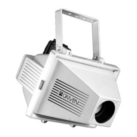
- Page 1 Foglio di Istruzioni Owner’s Manual GOBOCLIP GR 0444 CDM-SA/T 150W FI-0444 Rev. 0 14-06-2001...
-
Page 2: Table Of Contents
INDICE INDICE Pagina 1.0 CONTENUTO DELL’IMBALLAGGIO 2.0 SICUREZZA 3.0 INSTALLAZIONE DEL PROIETTORE 3.1 Montaggio della lampada 3.2 Regolazione lampada 3.3 Posizionamento del proiettore 3.4 Collegamento elettrico 4.0 USO DEL PROIETTORE 4.1 Installazione del gobo 4.2 Regolazione del gruppo ottico 4.3 Velocità di rotazione dell’immagine 5.0 MANUTENZIONE 6.0 INFORMAZIONI TECNICHE 7.0 PARTI DI RICAMBIO... -
Page 3: Contenuto Dell'imballaggio
1.0 CONTENUTO DELL’IMBALLAGGIO Controllate attentamente il contenuto del cartone e, in caso di danni al prodotto, contattate il Vs. trasportatore. Nell’imballaggio del presente proiettore sono contenuti i seguenti prodotti: n° 1 Foglio di Istruzioni; n° 1 proiettore GOBOCLIP; n°1 supporto d’installazione + viti di fissaggio. 2.0 SICUREZZA Prima di effettuare qualsiasi operazione sul proiettore, sconnettere fisicamente la linea di alimenta- zione staccando la spina (ad esempio durante la sostituzione della lampada). -
Page 4: Regolazione Lampada
3.2 Regolazione lampada Dopo il montaggio della lampada, può capitare che accendendo il proiettore il fascio luminoso non sia ben uniforme. E’ possibile la messa a punto agendo sulle 3 viti M3 poste sul coperchio cambio- lampada (vedi fig.3 e 4). Continuate la regolazione finche non ottenete una proiezione del fascio uniforme. -
Page 5: Collegamento Elettrico
Per il fissaggio del proiettore al pavimento, oppure al soffitto, è possibile utilizzare i fori (Ø8,5 e 10,5mm) posti sulla staffe di fissaggio del proiettore. Gli interassi delle forature sono rappresentati nelle fig.8 e 9. fig.8 fig.9 3.4 Collegamento elettrico - Utilizzando un cavo di alimentazione 3x1,5mm (sezione minima), cablate il morsetto posto all’interno della scatola in plastica come mostrato in fig.11;... -
Page 6: Uso Del Proiettore
4.0 USO DEL PROIETTORE 4.1 Installazione del gobo Per accedere al vano GOBO - LENTI - DIAFRAMMA aprite lo sportello anteriore del proiettore. Per eseguire questa operazione attenetevi alle istruzioni seguenti: - Svitate le 2 viti mostrate in figura 12 (A); - Aprite lo sportello, nel caso in cui il proiettore è... -
Page 7: Regolazione Del Gruppo Ottico
Ø53,3 mm. La dimensione massima dell’immagine è di Ø40 mm. Per dare colore all’immagine proiettata assieme ad un gobo metallico può essere inserito anche un filtro dicroico Ø53,3 mm. . Riposizionate l’anello elastico nella sua sede originale. fig.16 4.2 Regolazione del gruppo ottico Solamente dopo avere inserito l’immagine procedete con la regolazione del gruppo ottico per per- sonalizzare lo zoom e la messa a fuoco manuale. -
Page 8: Velocità Di Rotazione Dell'immagine
- il diaframma, che può scorrere sull’asta, permette di regolare il contorno immagine rendendolo più definito. Dopo avere eseguito tutte le regolazioni necessarie per ottenere la proiezione dell’immagine nella dimensione desiderata, accertatevi che le lenti e il diaframma siano saldamente fissati nella loro posizione di lavoro. -
Page 9: Manutenzione
5.0 MANUTENZIONE Il proiettore non richiede una manutenzione particolare, infatti essendo certificato IP55 esso è total- mente isolato dagli agenti esterni. Per assicurare la massima funzionalità e la massima resa ottica si raccomanda comunque di attenersi alle seguenti istruzioni: - Pulite le lenti, ed eventualmente il dicroico dell’immagine, poichè persino un sottilissimo strato di polvere può... -
Page 10: Parti Di Ricambio
Le viste esplose, lo schema elettrico, il diagramma elettronico e la brochure promozionale del pro- dotto sono disponibili su richiesta. La responsabilità di Griven S.r.l. cessa all’atto della consegna del materiale al vettore: reclami per eventuali danni dovuti al trasporto dovranno essere indirizzati direttamente al corriere. -
Page 11: Packing
1.0 PACKING Check the content of the box carefully and in case of damage contact your forwarder immediately. The following items are included in the box: n° 1 instructions leaflet; n° 1 GOBOCLIP unit; n° 1 mounting plate and fixing screws. 2.0 SAFETY Disconnect the lantern from mains supply before replacing the lamp or servicing the unit. -
Page 12: Lamp Adjustment
3.2 Lamp adjustment Adjust the three screws depicted in picture 3 should not the light output be completely even. The rotation of these screws will allow the best lamp adjustment for the perfect focusing of the image projection (see pictures 3 and 4). Pict. -
Page 13: Electrical Connection
Ø8.5 and Ø10.5mm holes are provided in the support brackets to fix the lantern to the ceiling or to the floor (see pict.8 and 9 for wheelbases dimensions). Pict. 8 Pict. 9 3.4 Electrical connection - Connect a 3x1.5 mm supply cable to the connector located in the plastic box as shown in picture 11;... -
Page 14: Using The Projector
4.0 USING THE PROJECTOR 4.1 Installing the gobo pattern Open the front panel of the unit to access the gobo pattern and optic group housing. Follow the instructions below to install the gobo pattern: - Remove the two screws (A) shown in picture 12; - Open the panel, lift it and use the metal support (B) to keep it up (see picture 13). -
Page 15: Optic Group Adjustment
Ø53,3 mm can be put in front of the metal gobo if you want to provide your image with colour. Lay the metal ring back into its original position once the gobo and the filter have been set in the slot. -
Page 16: Image Rotation Speed
Use the diaphragm that runs on the cylindrcal pivot to adjust the image definition and outline. When the required angle aperture is adjusted and the image perfectly focused, tighten the fixing knobs making sure the objective and the lenses are in their operational position which corresponds to them leaning against the support pivot shown in picture 19. -
Page 17: Maintenance
5.0 MAINTENANCE This unit is certified to an IP55 protection against all kinds of weather conditions and therefore it does not require a regular maintenance. To obtain the maximum light output and a durable life for the unit please follow instructions below: - clean lenses, objective and additional dichroic filter as even a thin layer of dust can reduce the light output and scatter the beam;... -
Page 18: Spare Parts
The exploded diagram, the eletric wiring scheme, the electronic layout and the promotional bro- chure are available on request. Griven S.r.l. shall be under no liability for any loss or demage in transit. Claims must be adressed directly to the forwarder. - Page 20 WORLD LIGHTING CHALLENGE Professional Lighting Manufacturer Via Bulgaria, 16 - 46042 CASTEL GOFFREDO (MN) Telefono 0376/779483 - Fax 0376/779682 - 0376/779552 http://www.griven.com/ e-mail griven@griven.com http://www.griven.it/ e-mail griven@griven.it...
Need help?
Do you have a question about the GR 0444 and is the answer not in the manual?
Questions and answers